
Caliper body for disk brake

a disc brake and caliper body technology, applied in the direction of axially engaging brakes, brake types, braking elements, etc., can solve the problems of irresolubility structural weakness, completely unsuitable for vehicles requiring high braking performance, and completely unsuitable for heat evacuation

Active Publication Date: 2015-12-15
FRENI BREMBO SPA
View PDF7 Cites 8 Cited by
  • Summary
  • Abstract
  • Description
  • Claims
  • Application Information

AI Technical Summary

Benefits of technology

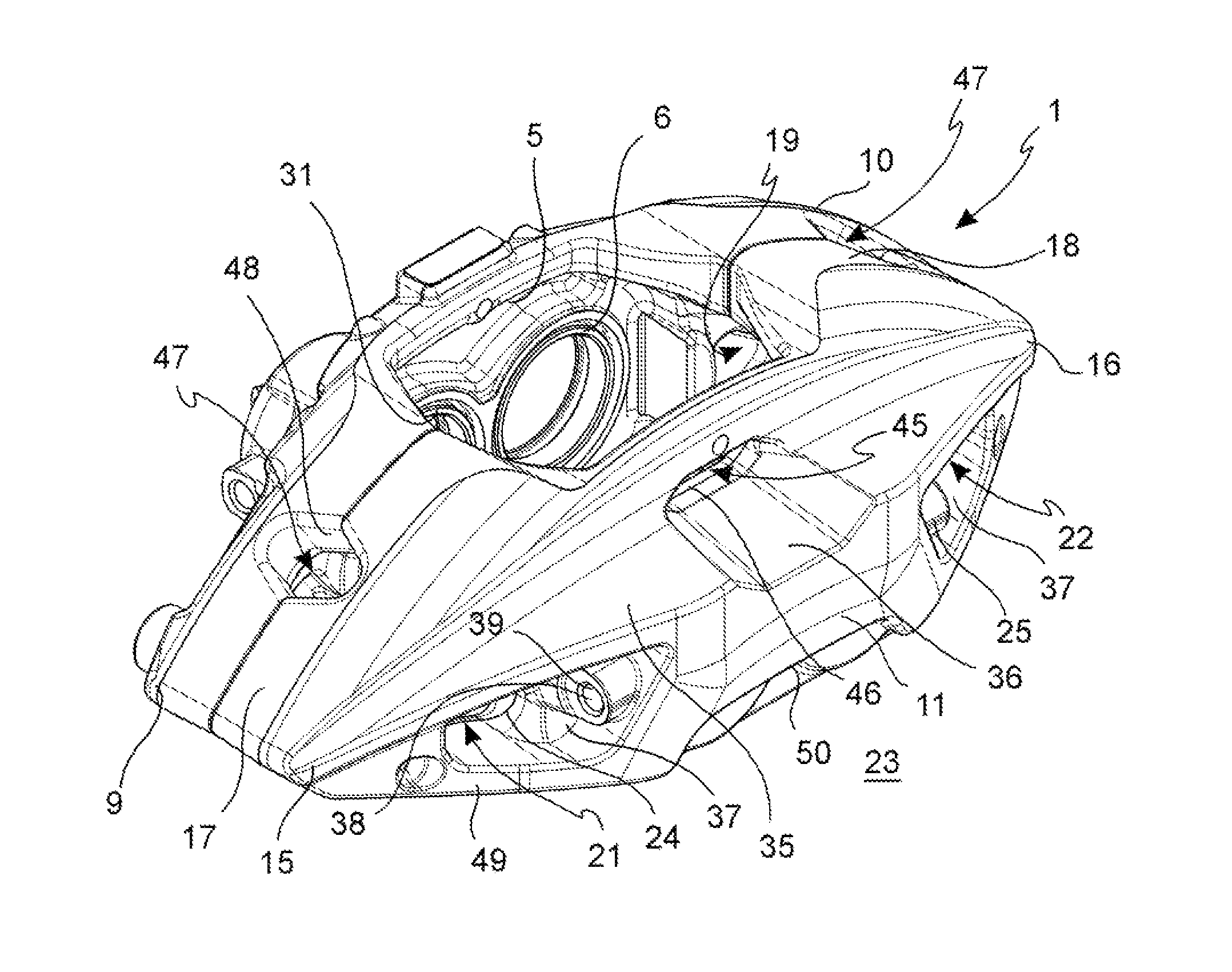
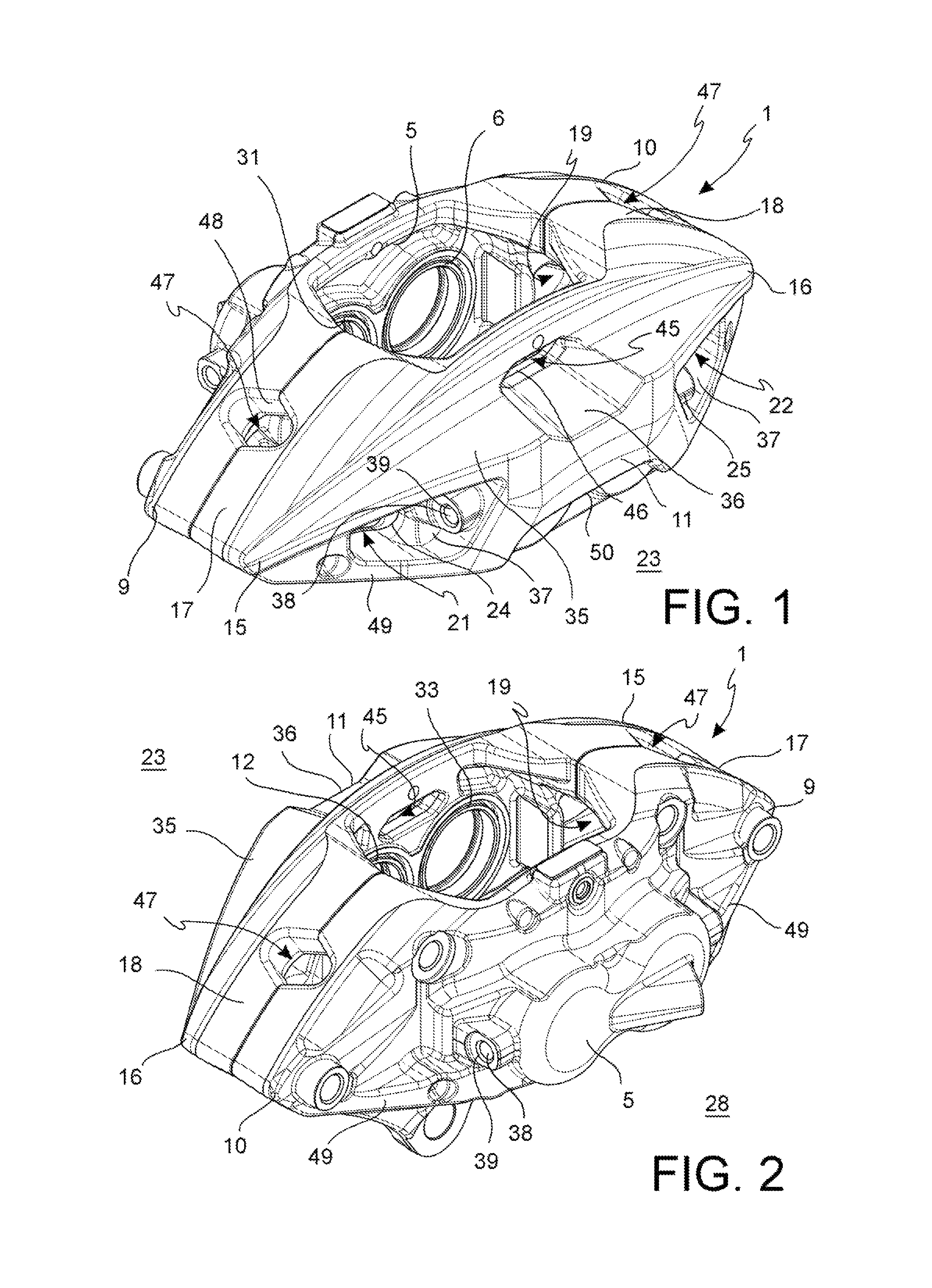
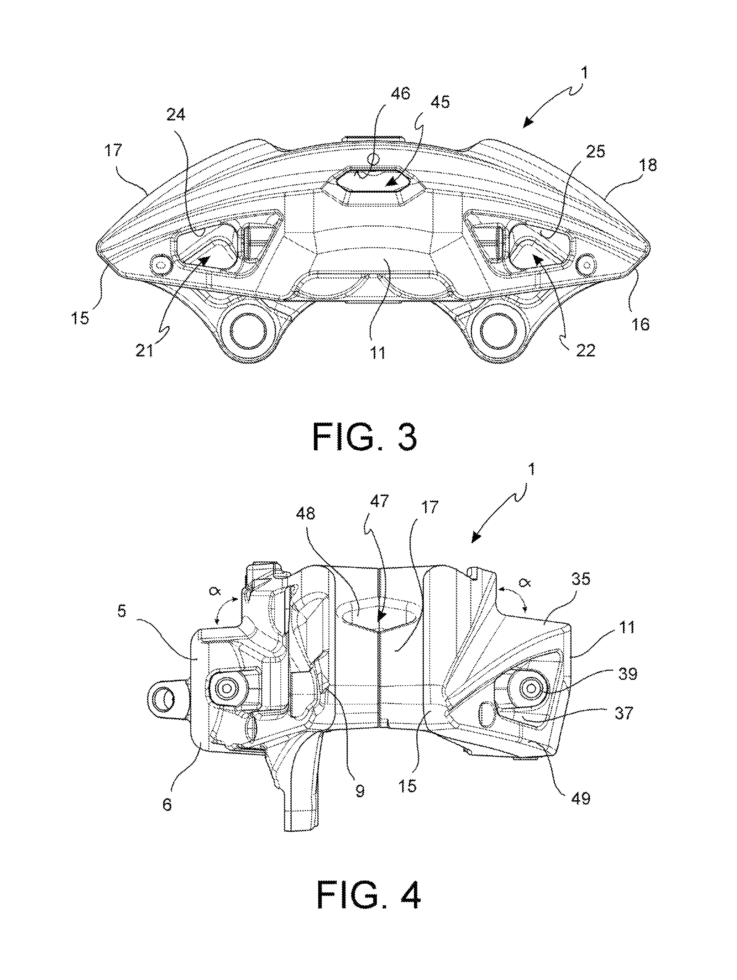
[0018]By virtue of the central opening, the heat generated during the braking action is not built up in the pocket of the caliper body housing the pad, but it finds, above the cylinders, this axial central opening from which it can exit, thus avoiding to bring the brake fluid adapted to influence in output the piston to boil.
[0020]By virtue of the proposed solution, the caliper body is particularly suitable for applications that generate strong structural stresses, avoiding substantial deformations of the caliper body and also avoiding pliancy feels of the braking system to the vehicle user. At the same time, by virtue of the proposed solution, it is possible to suitably ventilate the portion of the caliper body in the proximity of the cylinders and, in accordance with a further embodiment, also the disc immediately downstream, or upstream, of the brake pads.
[0021]At the same time, the proposed solution allows lightening the structure of the caliper body, avoiding anyhow structural weakenings. In particular, by virtue of the proposed solution, it is possible to avoid weakening the connection bridges of the enlarged portions facing the disc braking surfaces, and in particular to avoid weakening the connecting portions of these bridges to the enlarged portions, where, on the contrary, the maximum structural rigidity of the caliper body is maintained.

Problems solved by technology

As stated above, these solutions are completely unsuitable for vehicles requiring high braking performance, since they turn out to be particularly poor in both their ability to apply a braking force to the brake disc, and in their pliant structure.
Particularly, these solutions have connection areas between enlarged portions thereof that are suitable to face the brake disc, and bridges arranged astride of the disc, which are interested by openings and are irresolubly structurally weak.
This known solution is completely unsuitable to evacuate the heat built up during the braking action at the pads and moreover in the proximity of the pistons housed in the cylinders and projecting in pockets receiving the pads, in which pockets the heat generated during the braking action is built up.

Method used


Image

  • Caliper body for disk brake
  • Caliper body for disk brake
  • Caliper body for disk brake

Examples


Embodiment Construction

[0033]With reference to the above-mentioned Figures, a caliper body 1 of a disc brake caliper 51 is suitable to arrange astride of a brake disc 2 [FIG. 10].

[0034]Said brake disc 2 has a first braking surface 3, or vehicle side braking surface, and an opposite second braking surface 4, or wheel side braking surface.

[0035]Said braking surfaces 3, 4 are coaxial to an axis of rotation X-X of the brake disc 2.

[0036]Said axis of rotation X-X defines an axial direction A-A and a direction orthogonal thereto and directed radially to the disc R-R, as well as a further direction orthogonal or circumferential or tangential T-T to said brake disc 2.

[0037]Said caliper body 1 comprises a first vehicle side elongated portion 5 that is adapted to face said first braking surface 3 of the brake disc 2 [from FIG. 1].

[0038]Said elongated portion 5 comprises at least one first vehicle side piston seat, or vehicle side cylinder, that is adapted to seat a first piston 7. Said piston 7 may be biased with a...


PUM


Abstract

A caliper body (1) of a disc brake caliper, said body being adapted to arrange astride of a brake disc, said body (1) comprising a first (5) and a second (11) wheel side elongated portion, the second wheel side portion comprises at least one wheel side opening (21; 22; 45) which places a channel for receiving the disc in communication with the outside of the wheel side caliper body (23), and wherein said at least one opening (21; 22; 45) is an axial central opening (45) which places said channel for receiving the disc in communication with the outside of the wheel side caliper body (23), and wherein said axial central opening (45) has a closed edge which delimits said opening at a face thereof substantially in axial direction, and wherein said at least one axial central opening (45) is arranged at least partially substantially radially overlapping at least one wheel side cylinder (12; 33), wherein said at least one axial central opening (45) is arranged substantially in the center of said second wheel side elongated portion.

Description

FIELD OF THE INVENTION[0001]The present invention relates to a caliper body for a disc brake caliper.[0002]In particular, the present invention relates to a body for disc brake caliper of the fixed type, i.e., one that has, when it is mounted on a vehicle suspension, housings for thrust means or pistons arranged on both its side located towards the vehicle, and housings for thrust means or pistons arranged on its opposite side, i.e., facing the vehicle wheel.[0003]As it is known, these fixed caliper bodies are used mainly for high-performance vehicles or vehicles having a considerable mass to be braked. In fact, it is known that these fixed caliper bodies have a considerable strength, capable of withstanding also severe braking actions without showing a flexibility such as to compromise the braking itself and of avoiding to compromise the important braking readiness feel for the vehicle driver.[0004]It is also known that this important characteristic of strength, or mechanical rigid...

Claims


Application Information

Patent Timeline
Patent Type & Authority Patents(United States)
IPC IPC(8): F16D65/847F16D65/00F16D55/228
CPCF16D65/847F16D55/228F16D65/0075
Inventor PREDA, MASSIMOPUDDU, ARMANDOSCOTTI, FABIOCRIPPA, CRISTIAN
Owner FRENI BREMBO SPA
Learn More