Image formation apparatus having cleaning mode to clean charging device configured to charge image carrier

a technology of image carrier and cleaning mode, which is applied in the direction of electrographic process apparatus, instruments, corona discharge, etc., can solve problems such as image defects, and achieve the effect of minimizing degradation of throughput and efficient removal of extraneous matter

Active Publication Date: 2015-12-08
OKI ELECTRIC IND CO LTD
View PDF2 Cites 0 Cited by
  • Summary
  • Abstract
  • Description
  • Claims
  • Application Information

AI Technical Summary

Benefits of technology

[0008]An object of an embodiment of the invention is to efficiently remove the extraneous matter that adhered to the charge device and minimize the degradation of throughput by optimizing the execution frequency of the cleaning mode.
[0010]According to this aspect of the invention, it is possible to efficiently remove extraneous matter, such as toner's external additives, adhered to the charge device while minimizing degradation of the throughput.

Problems solved by technology

This causes a failure in charging the photoreceptor drum, thus leading to image defects.

Method used


Image

  • Image formation apparatus having cleaning mode to clean charging device configured to charge image carrier
  • Image formation apparatus having cleaning mode to clean charging device configured to charge image carrier
  • Image formation apparatus having cleaning mode to clean charging device configured to charge image carrier

Examples


first embodiment

(A-2) Operation of First Embodiment

[0073]Next, a description is given of the operation of image formation apparatus 10 according to the first embodiment in detail with reference to the drawings.

(A-2-1) Operation in Printing Mode

[0074]First, the operation of the printing mode in image formation apparatus 10 is described.

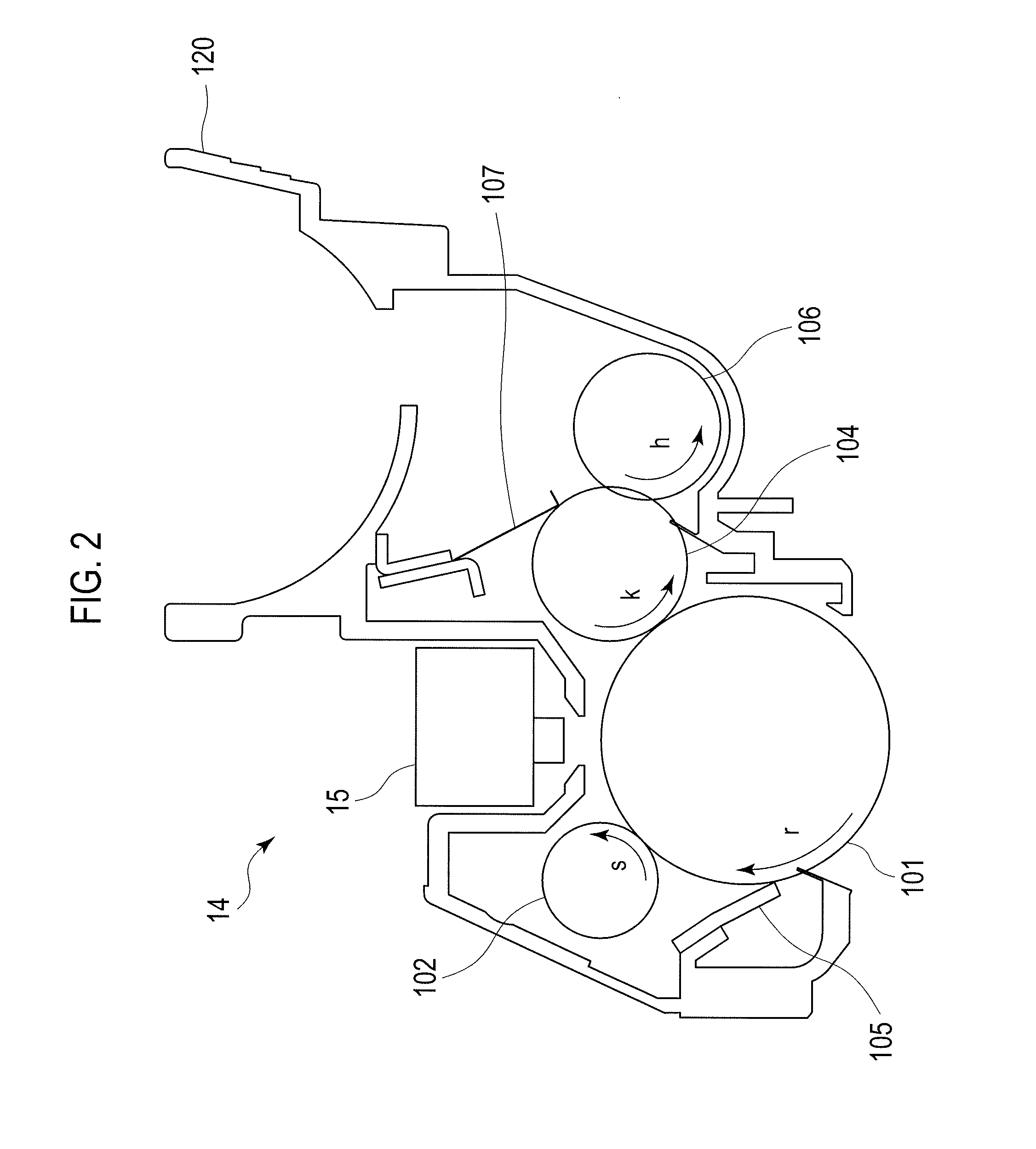
[0075]In FIG. 2, photoreceptor drum 101 is rotated at a predetermined circumferential velocity in the direction of arrow r of FIG. 2 by motor 501 as the driving unit.

[0076]Charge roller 102, which is provided in contact with the surface of photoreceptor drum 101, rotates in the direction of arrow s of FIG. 2 while being supplied with a direct-current voltage of about −1000 V by charge roller voltage power supply (CHB) 522 (see FIG. 3). The supplied voltage of about −1000 V is applied to the surface of photoreceptor drum 101, and the surface of photoreceptor drum 101 is uniformly charged to −500 V. Charge roller 102 rotates in the opposite direction to that of photorec...

second embodiment

(B) Second Embodiment

[0236]Next, a description is given of a second embodiment of the image formation apparatus of the invention in detail with reference to the drawings.

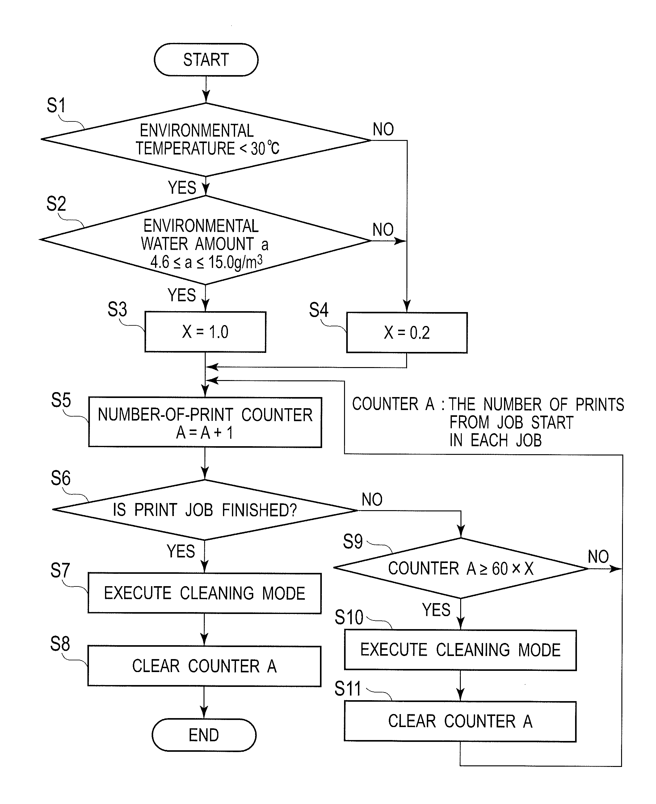
[0237]The rubber material of the cleaning blade changes in its physical properties depending on the environment. For example, the rubber material is more likely to be hardened in the LL environment. When the rubber material of the cleaning blade is hardened, the ability thereof to scrape the toner on the photoreceptor drum off is degraded. Accordingly, toner slips past the blade, and much more extraneous matter (external additives) tends to adhere to the charge roller.

[0238]The external additives as the extraneous matter are therefore deposited on the surface of the charge roller more quickly in the LL environment than in the HH environment. Accordingly, the portion where external additives are deposited has a low density, and one or more white vertical streak(s) is more likely to appear in the prints.

[0239]If the e...


PUM


Abstract

An image formation apparatus includes an image carrier, a charge device configured to charge the surface of the image carrier, a development device configured to pass a developer to an electrostatic latent image on the image carrier formed by exposure, a transfer device configured to transfer a developer image formed on the image carrier onto a medium, a remover device configured to remove the developer on the image carrier, and a controller configured to control a cleaning mode for removing extraneous matter adhered to the surface of the charge device at a time other than the time for the process of exposing the image carrier, and to change the execution frequency of the cleaning mode in accordance with an environmental condition.

Description

CROSS REFERENCE TO RELATED APPLICATIONS[0001]This application claims priority based on 35 USC 119 from prior Japanese Patent Application No. 2013-269820 filed on Dec. 26, 2013, entitled “IMAGE FORMATION APPARATUS”, the entire contents of which are incorporated herein by reference.BACKGROUND OF THE INVENTION[0002]1. Field of the Invention[0003]This disclosure relates to an image formation apparatus.[0004]2. Description of Related Art[0005]In a conventional image formation apparatus, an image is developed using toner (a developer) on the surface of a photoreceptor drum, and in some cases, a part of the toner is not properly transferred and remains on the surface of the photoreceptor drum. The remaining toner is removed by a cleaning blade in a process after the process of transfer to the surface of the photoreceptor drum. However, some of the toner not removed by the cleaning blade further adheres to the surface of a charge roller on a downstream side in the rotation direction of the ...

Claims


Application Information

Patent Timeline
Patent Type & Authority Patents(United States)
IPC IPC(8): G03G15/00G03G15/02
CPCG03G15/0225
Inventor KOSASA, TSUTOMUKOIDO, KENJI
Owner OKI ELECTRIC IND CO LTD
Why Eureka
Try Eureka