
Vehicle control apparatus

a technology for controlling apparatus and vehicles, applied in brake systems, machines/engines, instruments, etc., can solve problems such as deterioration in drivability, and achieve the effect of preventing drivability from being deteriorated and reducing the driving force outpu

Active Publication Date: 2015-12-01
TOYOTA JIDOSHA KK
View PDF15 Cites 3 Cited by
  • Summary
  • Abstract
  • Description
  • Claims
  • Application Information

AI Technical Summary

Benefits of technology

The vehicle control system described in this patent can reduce the amount of force provided by the engine when the driver presses both the accelerator and brake pedals at the same time. This helps to maintain good driving performance on normal roads. However, when the vehicle is driving on a bad road, the system allows the engine to generate the force needed to keep the vehicle moving. This prevents the vehicle from becoming difficult to control and ensures smooth driving.

Problems solved by technology

Therefore, there are some cases in which the simultaneous depressions of the accelerator pedal and the brake pedal as previously mentioned are apt to lead to deterioration in drivability.

Method used


Image

  • Vehicle control apparatus
  • Vehicle control apparatus
  • Vehicle control apparatus

Examples


Embodiment Construction

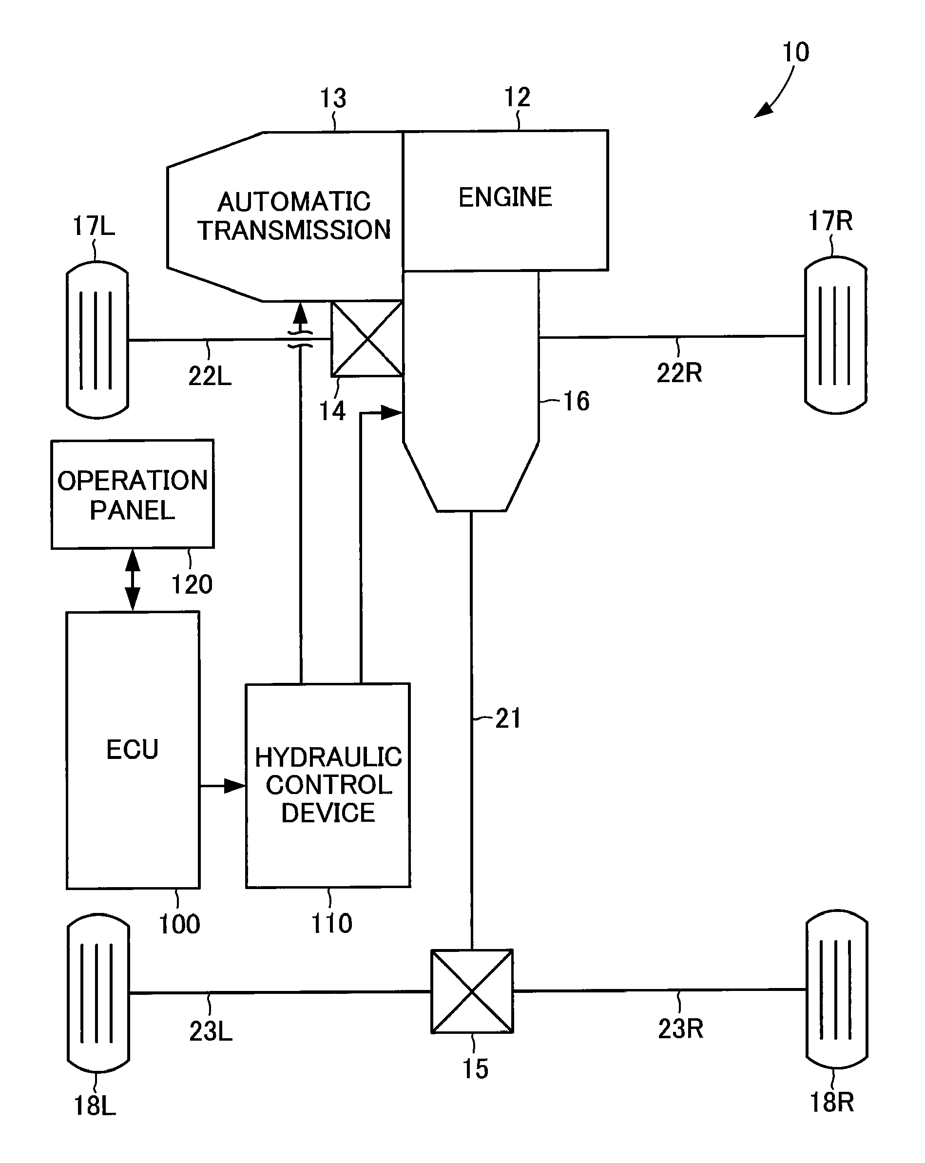
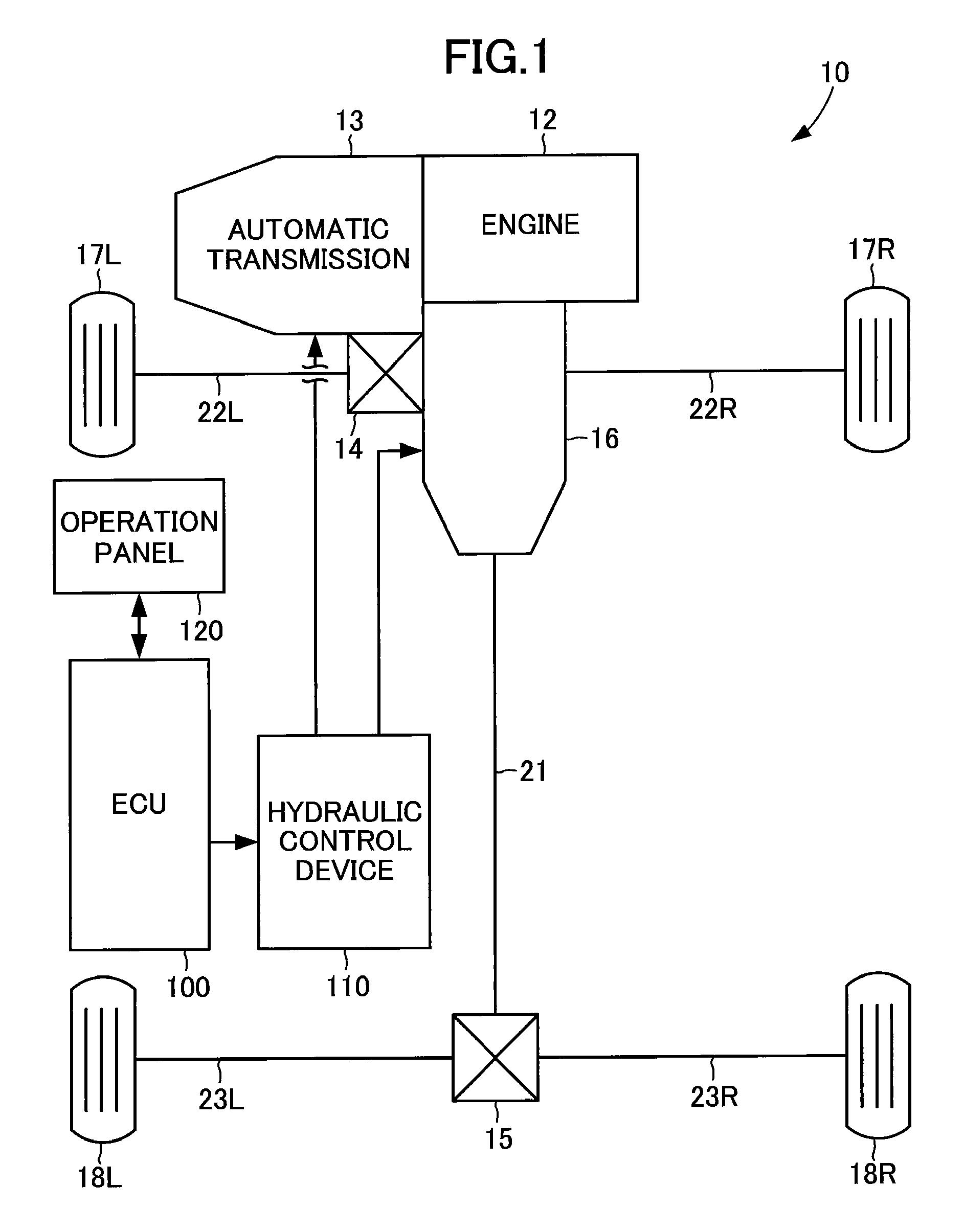
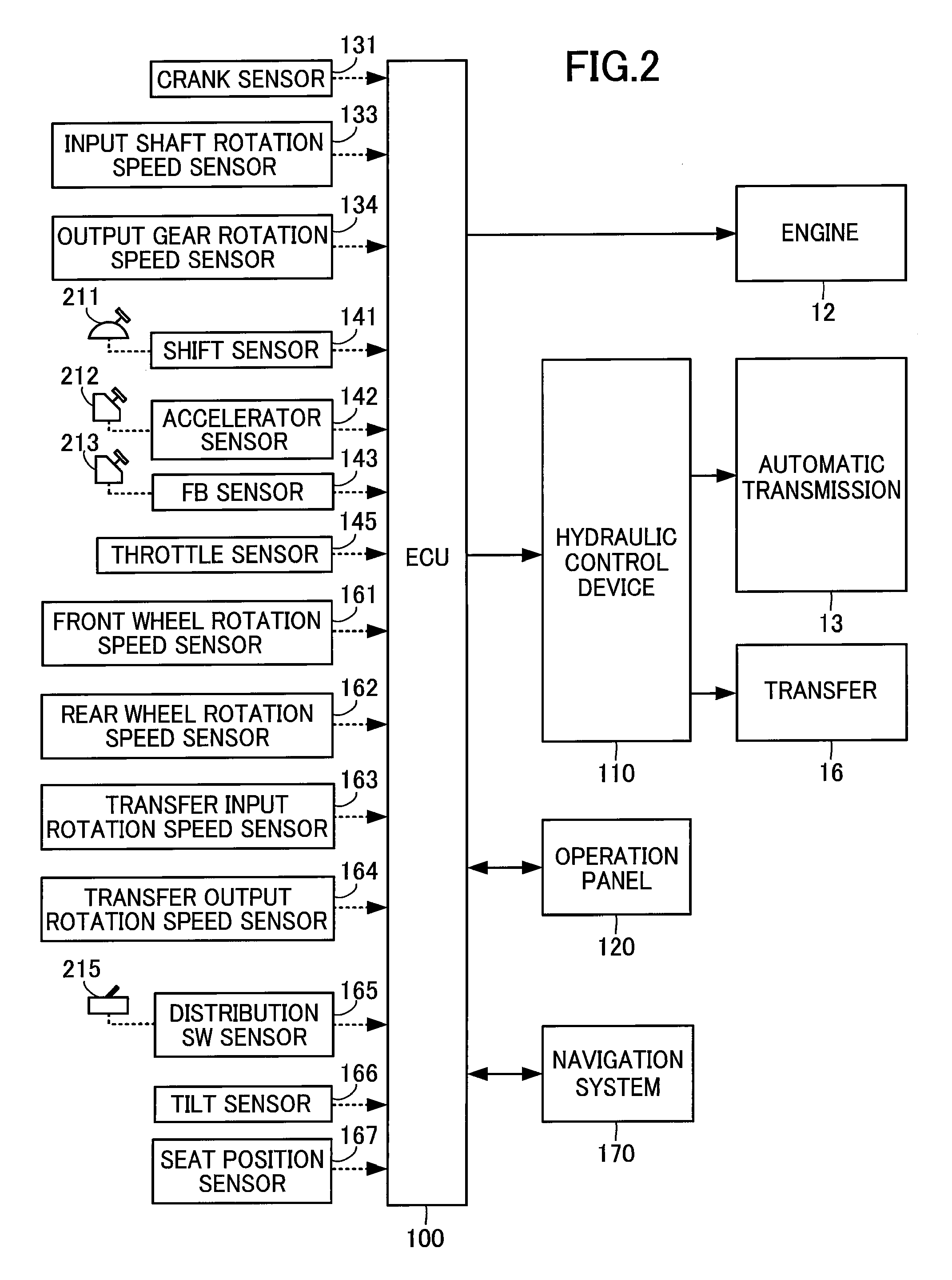
[0132]The embodiments of the invention will be described hereinafter with reference to the drawings. First, the construction of a vehicle having a control apparatus according to the embodiment of the present invention will be described with reference to the schematic block diagram of the vehicle shown in FIG. 1 and the schematic block diagram of the vehicle control shown in FIG. 2.

[0133]As shown in FIG. 1, a vehicle 10 according to the present embodiment comprises an engine 12 serving as a power source, an automatic transmission 13 that transmits a torque generated by the engine 12 and forms transmission stages corresponding to the travel conditions of the vehicle 10, a front differential mechanism 14 that distributes the torque transmitted from the automatic transmission 13 to left and right front drive shafts 22L, 22R, a rear differential mechanism 15 that distributes the torque transmitted by a propeller shaft 21 to left and right rear drive shafts 23L, 23R, and a transfer 16 tha...


PUM


Abstract

Disclosed is a vehicle control apparatus which can prevent drivability from being deteriorated. The ECU is operative to determine whether the previously depressed brake is in the “ON” or “OFF” state when the vehicle is determined as being not travelling on a bad road, the accelerator being in the “ON” state, and the brake being in the “ON” state. When the ECU is operative to determine that the previously depressed brake is in the “OFF” state, and the vehicle is in the reduced speed state, the ECU is operative to perform the reduction process of the engine output under the condition that the simultaneous depressions of the accelerator and brake pedals are held for less than 10 seconds, and the vehicle speed is 7 km / hr or more. When, on the other hand, the ECU determines that the vehicle is travelling on the bad road, the ECU is operative not to perform the reduction process.

Description

[0001]This is a 371 national phase application of PCT / JP2009 / 006955 filed 17 Dec. 2009, the contents of which are incorporated herein by reference.TECHNICAL FIELD[0002]The present invention relates to a vehicle control apparatus, and more particularly to a vehicle control apparatus that controls the output of a power source.BACKGROUND ART[0003]In general, a vehicle has three fundamentally necessary abilities including a “driving force” as an ability of “advancing”, a “steering force” as an ability of “turning”, and a “braking force” as an ability of “stopping”.[0004]The “driving force” is a power, i.e., a torque generated by a power source of an internal combustion engine (hereinafter simply referred to as “engine”) in response to such an amount of depression of an accelerator pedal and transmitted through a transmission to driving wheels to be obtained as a frictional reaction force of the driving wheels and a road surface allowing the driving wheels to travel thereon. The “steerin...

Claims


Application Information

Patent Timeline
Patent Type & Authority Patents(United States)
IPC IPC(8): B60W30/18B60T7/04F02D29/02B60T7/12B60W10/06B60W10/119B60W30/192B60W50/10
CPCB60W30/18072B60T7/042B60T7/12B60W10/06B60W10/119B60W50/10F02D29/02B60W30/192B60W2550/147B60T2260/08B60W2520/10B60W2540/12B60W2552/35
Inventor OISHI, TOSHIYAKAIGAWA, MASATOTAKAGI, MASASHISHIMADA, MICHIHITOMINASE, YUKIOKAYA, KENICHIMIYAZAKI, TSUTOMU
Owner TOYOTA JIDOSHA KK
Learn More