
Optically interleaved photonic analog to digital converters

a technology of optical interleaved photonic analog and digital converter, applied in the direction of digital transmission, phase-modulated carrier system, electromagnetic transmission, etc., can solve the problem of significant constraining the potential of these and other communication systems

Active Publication Date: 2015-11-24
ROCKWELL COLLINS INC
View PDF67 Cites 21 Cited by
  • Summary
  • Abstract
  • Description
  • Claims
  • Application Information

AI Technical Summary

Benefits of technology

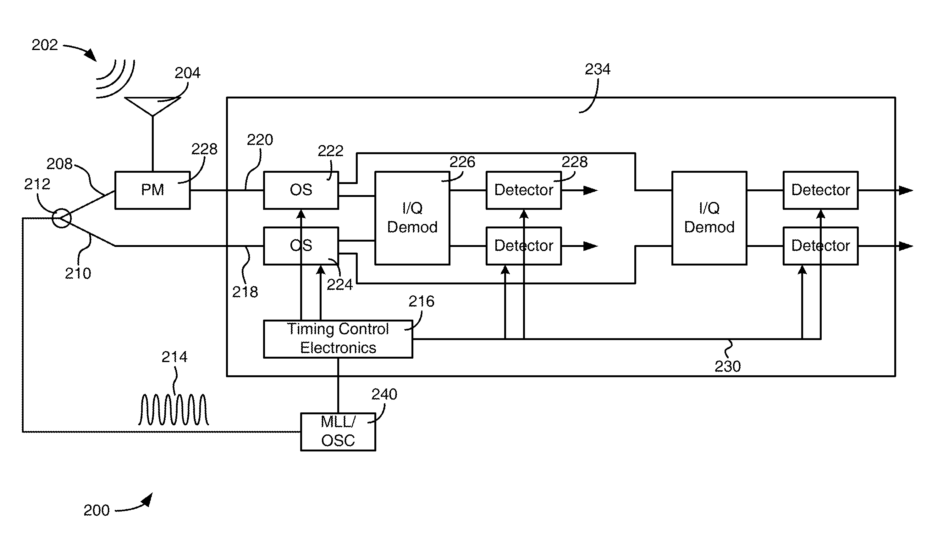
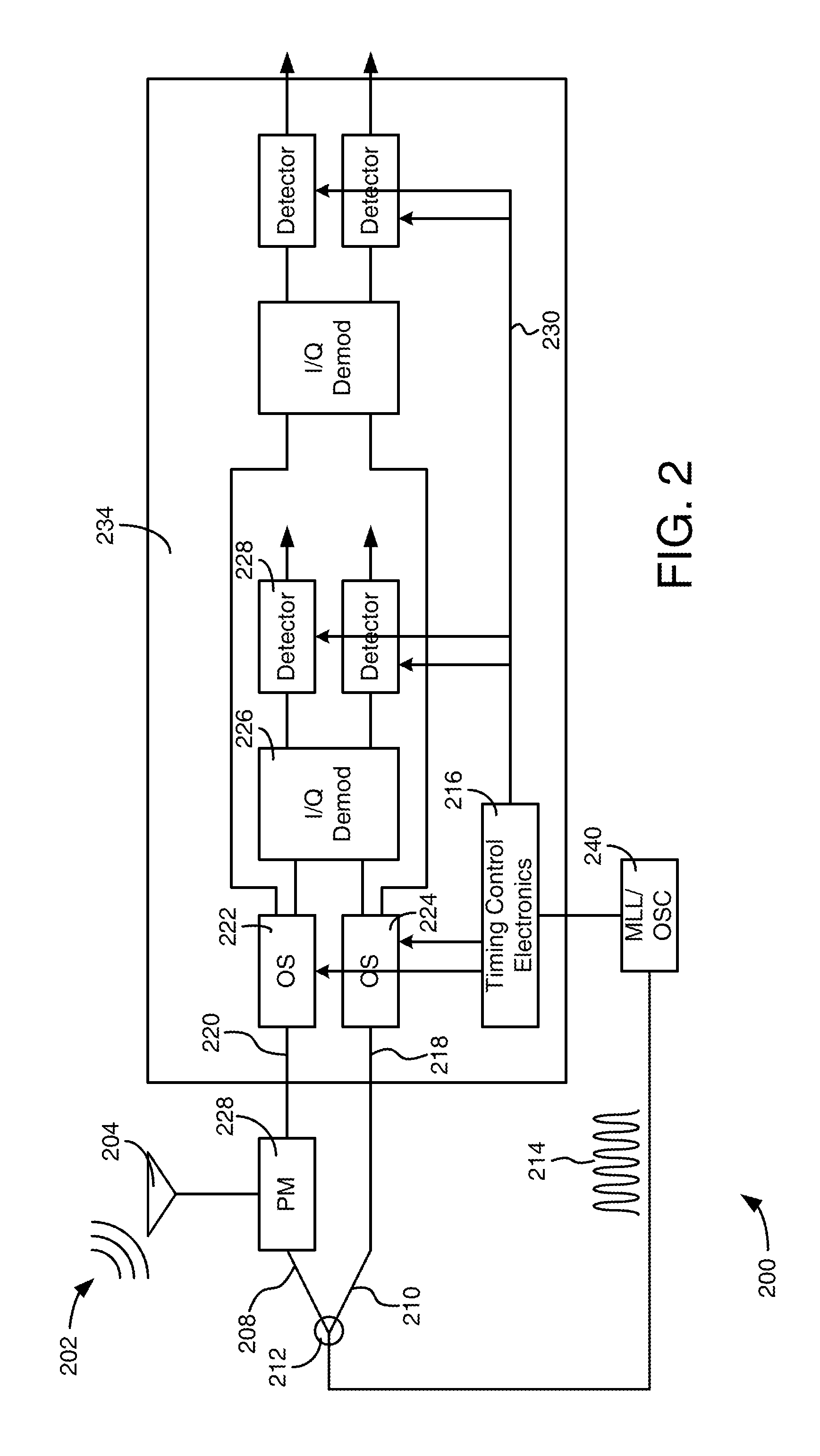
The patent describes a system and method for processing a received analog signal using photonic processing components. The system includes a receiver, a pulsed laser, and a timing control circuitry. The receiver detects the analog signal and the pulsed laser produces a series of optical pulses at a predetermined sampling rate. The timing control circuitry receives the optical pulses and produces a plurality of timing signals. The system also includes an optical splitter to split the optical pulses into two optical signals, a phase modulator to optically sample the analog signal using the first optical signal, and optical reference switches to time deinterleave the optical signals. The system further includes demodulators and track and hold amplifiers to process the optical signals. The technical effects of this patent include improved processing of analog signals and improved accuracy of the timing control.

Problems solved by technology

Fundamental performance limits of conventional ADCs significantly constrains the potential of these and other communication systems.

Method used


Image

  • Optically interleaved photonic analog to digital converters
  • Optically interleaved photonic analog to digital converters
  • Optically interleaved photonic analog to digital converters

Examples


Embodiment Construction

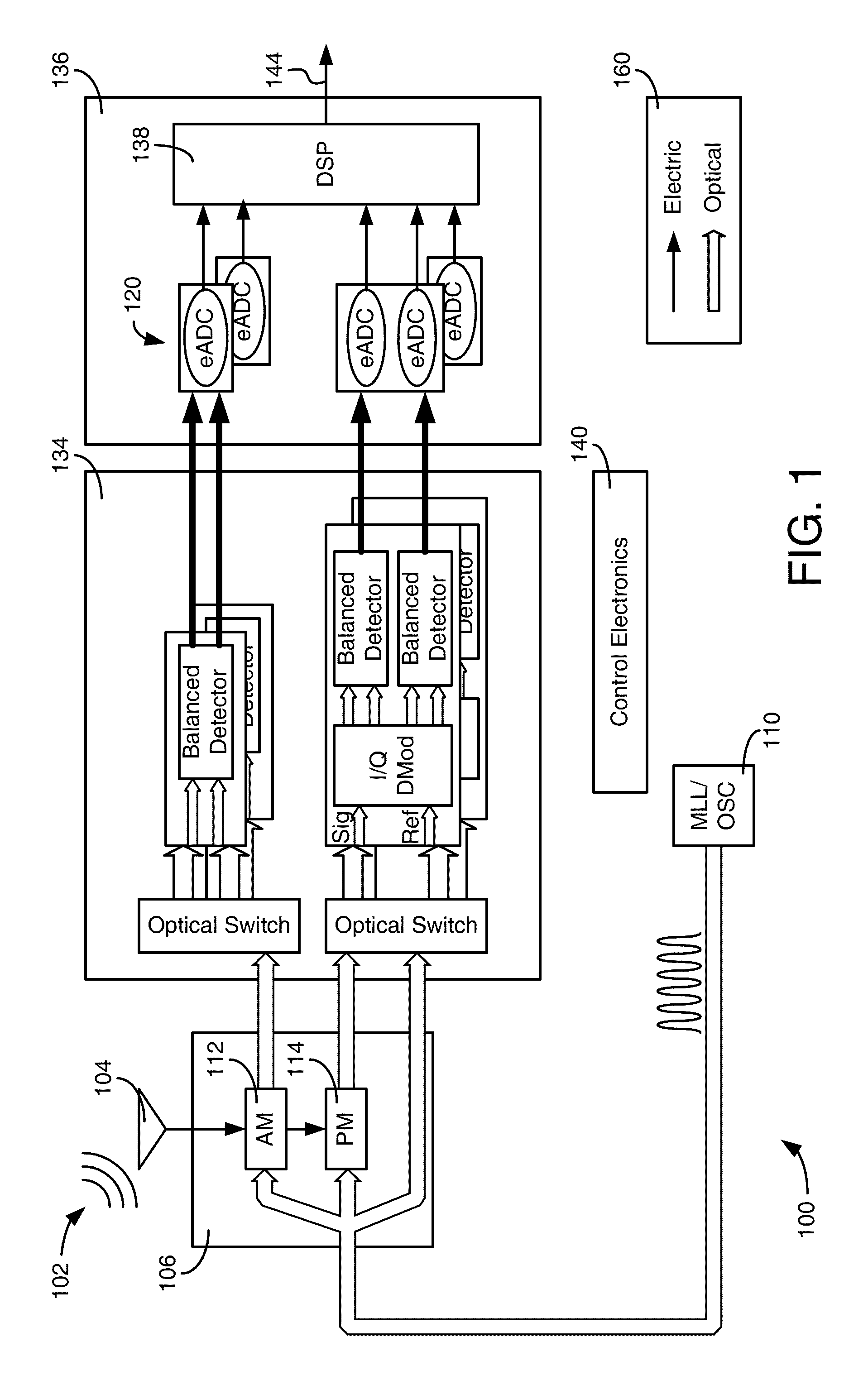
[0020]Before describing in detail the particular improved system and method, it should be observed that the invention includes, but is not limited to, a novel structural combination of optical components and not in the particular detailed configurations thereof. Accordingly, the structure, methods, functions, control and arrangement of components have been illustrated in the drawings by readily understandable block representations and schematic drawings, in order not to obscure the disclosure with structural details which will be readily apparent to those skilled in the art, having the benefit of the description herein. Further, the invention is not limited to the particular embodiments depicted in the exemplary diagrams, but should be construed in accordance with the language in the claims.

[0021]With reference to FIG. 1, a receiver 100 can be used in a several applications including but not limited to military applications, medical imaging applications, radio applications, or any o...


PUM


Abstract

A method of and system of processing a phase-modulated optical signal includes performing, by demodulators, demodulation of the phase-modulated optical signal and outputting optical demodulated signals. The processing further includes performing, by pairs of gated photo detectors respectively connected to the I / Q demodulators, photo detection of the demodulated signals. The processing further tracks and holds electronicversions of the demodulated signals with a track and hold amplifier.

Description

CROSS-REFERENCE TO RELATED PATENT APPLICATIONS[0001]The present application claims the benefit of and priority to and is a continuation-in-part of U.S. application Ser. No. 13 / 243,208, filed on Sep. 23, 2011 entitled “OPTICALLY INTERLEAVED ELECTRONIC ANALOG TO DIGITAL CONVERTERS” by Zanoni et al. (11CR245 ('803)), and claims the benefit of and priority to and is a continuation-in-part of U.S. application Ser. No. 13 / 787,202, filed on Mar. 6, 2012, entitled “OPTICAL SAMPLE AND HOLD SYSTEM AND METHOD” by Zanoni et al. (11CR368CIP (910)), which is a continuation-in-part of U.S. patent application Ser. No. 13 / 240,226 entitled “OPTICAL DESERIALIZATION WITH GATED DETECTORS: SYSTEM AND METHOD”, filed on Sep. 22, 2011, by Zanoni et al. (11CR368 ('813)), U.S. patent application Ser. No. 13 / 204,158 entitled “WIDE BAND DIGITAL RECEIVER: SYSTEM AND METHOD”, filed on Aug. 5, 2011, by Zanoni et al. (11CR278 ('811)), U.S. patent application Ser. No. 13 / 626,642 entitled “OPTICAL ANALOG-TO-DIGITAL C...

Claims


Application Information

Patent Timeline
IPC IPC(8): H04B10/00H04L27/22
CPCH04L27/223H04B10/90H04B2210/006
Inventor ZANONI, RAYMONDJEPSEN, KIM S.KING, OLIVER S.LALIBERTE, MARK A.
Owner ROCKWELL COLLINS INC
Learn More