
Systems and methods for environmental testing and evaluation of non-destructive inspection sensors

a non-destructive inspection and sensor technology, applied in the direction of instrumentation, vehicle testing, structural/machine measurement, etc., can solve the problems of sensor performance accuracy, sensor failure prematurely, sensor system and method subject to such known sensor systems and methods

Active Publication Date: 2015-11-24
THE BOEING CO
View PDF6 Cites 25 Cited by
  • Summary
  • Abstract
  • Description
  • Claims
  • Application Information

AI Technical Summary

Benefits of technology

The patent text describes a system and method for testing and evaluating sensors used for non-destructive testing (NDI) of structures. The new system offers advantages over existing methods. The technical effect is the provision of a reliable and efficient solution for environmental testing and evaluation of sensors used for NDI of structures.

Problems solved by technology

However, when the sensors of such known sensor systems and methods are subjected to adverse environmental conditions and / or varying temperature conditions, such as very high temperatures (e.g., 212° F.
(minus seventy-eight degrees Fahrenheit) or lower), the performance accuracy of the sensors may be affected or the sensors may prematurely fail.
If the performance accuracy of the sensors is affected, or the sensors prematurely fail while in use, the sensors may have to be removed and replaced.
This may result in increased labor and rework costs and increased out-of-service time of the aircraft.
Moreover, if the performance accuracy of the sensors is affected, or the sensors prematurely fail while in use, the structural health monitoring and damage detection of the structure may be delayed or impaired, which in turn, may delay or hinder maintenance of the structure that may be needed.
In addition, known sensor systems and methods for NDI may not be able to accurately detect the depth and location of internal damage to a structure, such as an aircraft structure, that may occur as a result of external impact to the structure, and in particular, if the external impact to the structure is not visible.
This may result in increased labor and rework costs and increased out-of-service time of the aircraft.

Method used


Image

  • Systems and methods for environmental testing and evaluation of non-destructive inspection sensors
  • Systems and methods for environmental testing and evaluation of non-destructive inspection sensors
  • Systems and methods for environmental testing and evaluation of non-destructive inspection sensors

Examples


example 1

[0078]FIG. 7 is an illustration of a plot 170 of test results 178 of NDI sensor output at an NDI sensor location number 6. As shown on the left side of FIG. 7, NDI sensor location numbers 1-22 were mounted and were divided between two rows indicated as Strip 1 and Strip 2, and NDI sensor location numbers 1-11 were on Strip 1, and NDI sensor location numbers 12-22 were on Strip 2. Plot portion 172 shows a top surface of Strip 1 and Strip 2 and does not show the NDI sensors 130 which are below the top surface. Plot portion 174 shows a view of the NDI sensors 130 below the top surface of the same Strip 1 and Strip 2 as shown on the left side of FIG. 7. The impact locations 175 are shown below the top surface of Strip 1 and Strip 2. An impact damage amplitude / color intensity indicated by an NDI sensor detected impact location image 176 is shown for NDI sensor location number 6 and shows the impact damage amplitude / color intensity, which was measured using a color scale. The more intense...

example 2

[0079]FIG. 8 is an illustration of a plot 180 of test results 178 of NDI sensor output at an NDI sensor location number 8. As shown on the left side of FIG. 8, NDI sensor location numbers 1-22 were divided between two rows indicated as Strip 1 and Strip 2, and NDI sensor location numbers 1-11 were on Strip 1, and NDI sensor location numbers 12-22 were on Strip 2. Plot portion 172 shows a top surface of Strip 1 and Strip 2 and does not show the NDI sensors 130 which are below the top surface. Plot portion 174 shows a view of the NDI sensors 130 below the top surface of the same Strip 1 and Strip 2 as shown on the left side of FIG. 8. The impact locations 175 are shown below the top surface of Strip 1 and Strip 2. An impact damage amplitude / color intensity indicated by an NDI sensor detected impact location image 182 is shown for NDI sensor location number 8 and shows the impact damage amplitude / color intensity, which was measured using a color scale. As shown in FIG. 8, the test resu...

example 3

[0080]FIG. 9 is an illustration of a plot 184 of test results 178a of NDI sensor output at an NDI sensor location number 12. As shown on the left side of FIG. 9, NDI sensor location numbers 1-22 were divided between two rows indicated as Strip 1 and Strip 2, and NDI sensor location numbers 1-11 were on Strip 1, and NDI sensor location numbers 12-22 were on Strip 2. Plot portion 172 shows a top surface of Strip 1 and Strip 2 and does not show the NDI sensors 130 which are below the top surface. Plot portion 174 shows a view of the NDI sensors 130 below the top surface of the same Strip 1 and Strip 2 as shown on the left side of FIG. 9. The impact locations 175 are shown below the top surface of Strip 1 and Strip 2. An impact damage amplitude / color intensity indicated by an NDI sensor detected impact location image 186 is shown for NDI sensor location number 12, which was measured using a color scale. The NDI sensor detected impact location image 186 also shows the ability of the NDI ...


PUM


Abstract

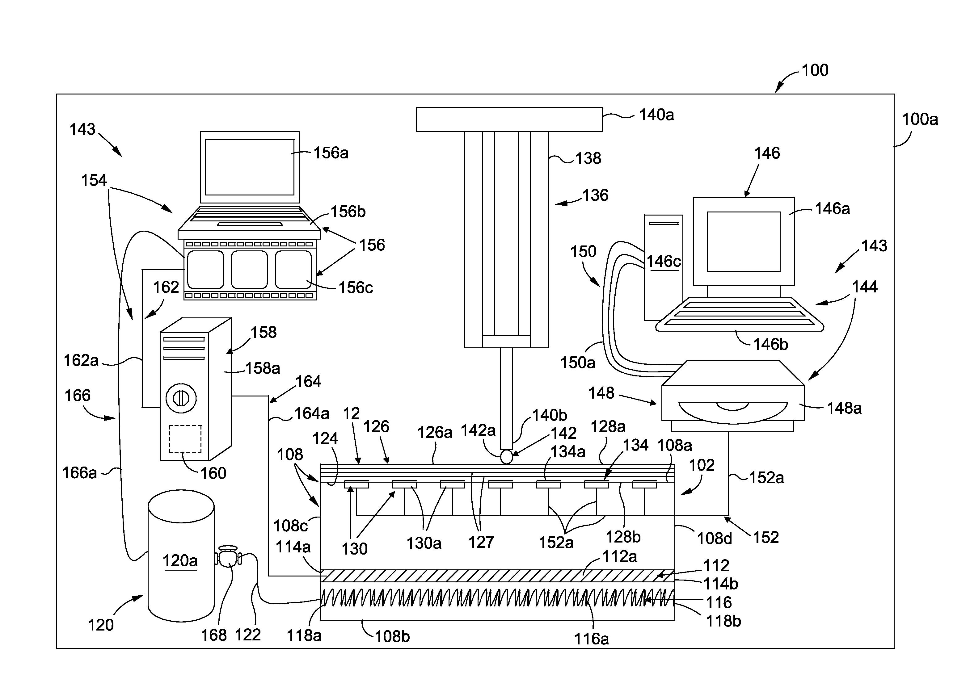
A system and method for environmental testing and evaluation of non-destructive inspection (NDI) sensors is provided. The system has a structure having a plurality of NDI sensors to be tested. The system further has an environmental chamber containing heating elements and cooling elements for heating and cooling the NDI sensors when the structure is secured to the environmental chamber. The system further has an impact testing assembly positioned over the structure for impacting the structure. The system further has a data acquisition computer subsystem coupled to the environmental chamber and coupled to the NDI sensors. The data acquisition computer subsystem controls and monitors the heating and cooling elements, and collects and processes temperature and impact data acquired by the NDI sensors.

Description

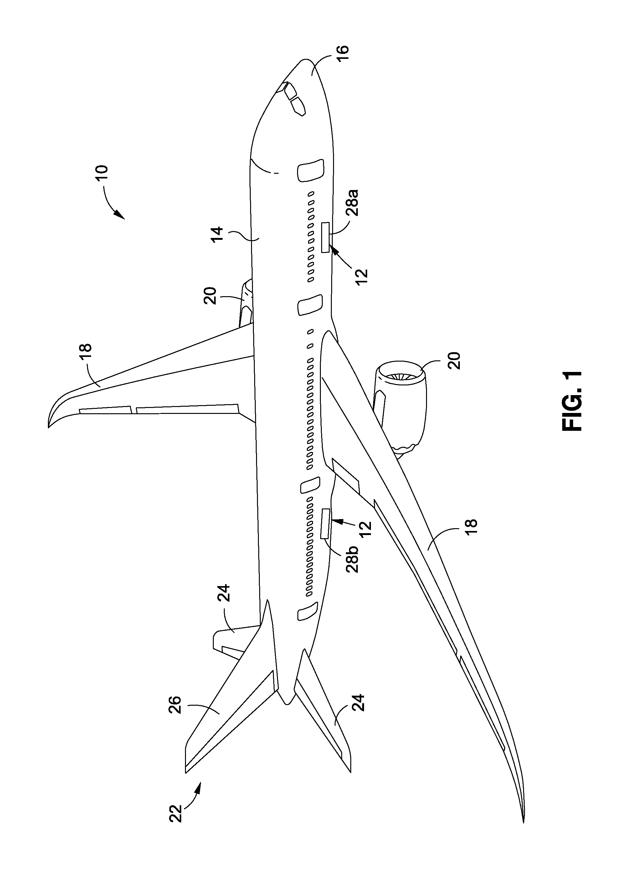
BACKGROUND[0001]1) Field of the Disclosure[0002]The disclosure relates generally to systems and methods for testing and evaluation of sensors, and more specifically, to systems and methods for environmental testing and evaluation of non-destructive inspection (NDI) sensors.[0003]2) Description of Related Art[0004]Non-destructive inspection (NDI) involves inspecting and evaluating a structure without damaging the structure or requiring its significant disassembly, and without impairing the structure's future use and serviceability. NDI is advantageous for many applications in which a thorough inspection of the exterior and / or interior of a structure is required. For example, NDI is typically used in the aircraft industry to inspect aircraft structures during manufacturing of the structures and / or once the structures are in-service.[0005]Various types of sensors may be used to perform NDI. Known sensor systems and methods for NDI exist that monitor the structural health, detect damage...

Claims


Application Information

Patent Timeline
IPC IPC(8): G06F11/00G06F17/00G01M99/00G01M17/00
CPCG01M99/00G01M17/00G06F17/00G01M7/08G01M99/002G06F11/00
Inventor SENIBI, SIMON D.HANSEN, JEFFREY M.
Owner THE BOEING CO
Learn More