
Methods of forming a cutting element for an earth-boring tool, a related cutting element, and an earth-boring tool including such a cutting element

a technology of cutting element and earthboring tool, which is applied in the direction of grinding device, other chemical processes, polishing compositions, etc., can solve the problems of pdc thermal damage, pdc that and is vulnerable to shear, compressive and tensile stresses, and is relatively more brittle than fully leached pd

Active Publication Date: 2015-11-24
ELEMENT SIX LTD +1
View PDF397 Cites 3 Cited by
  • Summary
  • Abstract
  • Description
  • Claims
  • Application Information

AI Technical Summary

Benefits of technology

The patent text describes a method of forming a cutting element for a drilling tool used in the earth-boring industry. The method involves using a supporting substrate and a volume of diamond particles made up of nanoparticles. These particles are processed under high temperature and pressure conditions to form a polycrystalline compact, which is then sintered to create a strong and durable cutting element. The resulting cutting element has improved mechanical properties and can withstand high drilling temperatures and pressures. Overall, this method allows for the production of efficient and effective cutting tools for the oil and gas industry.

Problems solved by technology

The presence of the catalyst material in the PDC may contribute to thermal damage in the PDC when the PDC cutting element is heated during use due to friction at the contact point between the cutting element and the formation.
However, a fully leached PDC is relatively more brittle and vulnerable to shear, compressive, and tensile stresses than is a non-leached PDC.
In addition, it is difficult to secure a completely leached PDC to a supporting substrate.
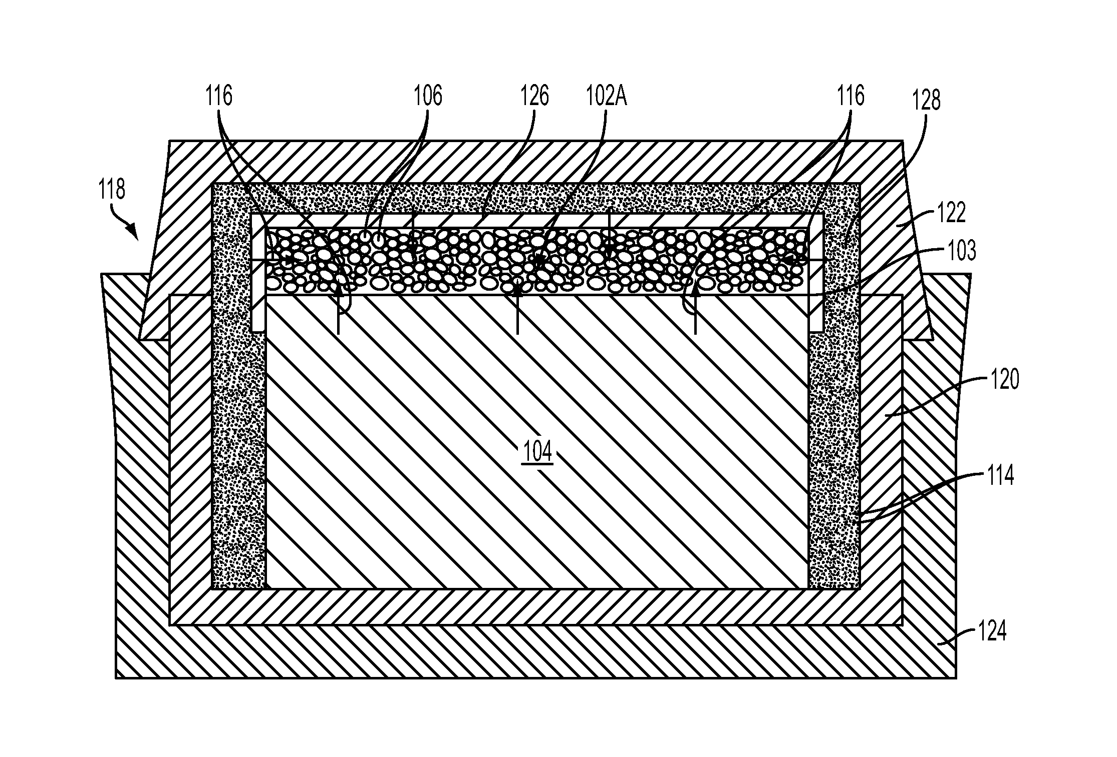
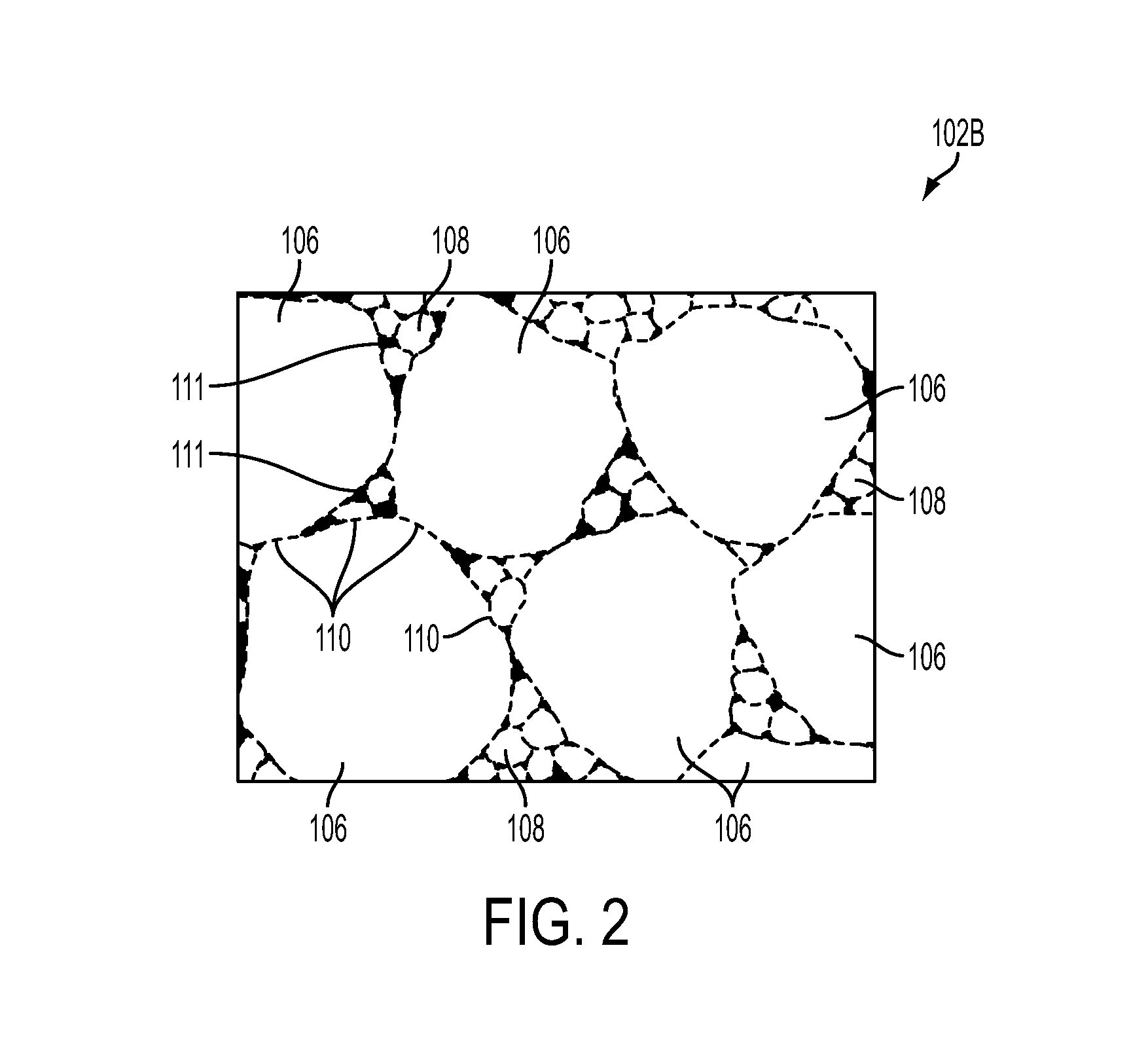
However, disadvantageously, as higher concentrations of nanoparticles are incorporated into the interstitial spaces, the “sweep” of catalyst material from the supporting substrate during subsequent HTHP processing is inhibited, resulting in formation of a nanoparticle-enhanced (“nanoparticle-enhanced”) PDC that may be poorly sintered at positions distal from an interface of the nanoparticle-enhanced PDC and the supporting substrate.

Method used


Image

  • Methods of forming a cutting element for an earth-boring tool, a related cutting element, and an earth-boring tool including such a cutting element
  • Methods of forming a cutting element for an earth-boring tool, a related cutting element, and an earth-boring tool including such a cutting element
  • Methods of forming a cutting element for an earth-boring tool, a related cutting element, and an earth-boring tool including such a cutting element

Examples


Embodiment Construction

[0017]The illustrations presented herein are, in some instances, not actual views of any particular cutting element insert, cutting element, drill bit, system or method, but are merely idealized representations which are employed to describe embodiments of the disclosure. Additionally, elements common between figures may retain the same numerical designation.

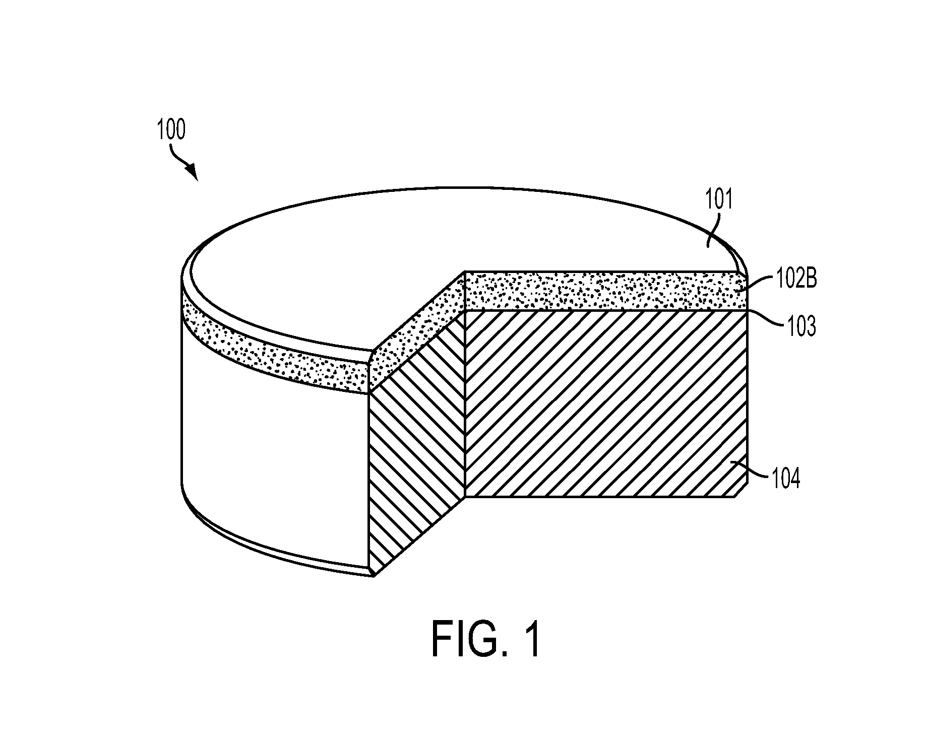
[0018]Embodiments of the disclosure include methods for forming a cutting element including a nanoparticle-enhanced polycrystalline compact, such as a nanoparticle-enhanced polycrystalline diamond compact (“PDC”), along with related cutting elements, and earth-boring tools including such cutting elements. The methods of the disclosure utilize at least one catalyst material to form the polycrystalline compact.

[0019]As used herein, the term “inter-granular bond” means and includes any direct atomic bond (e.g., covalent, metallic, etc.) between atoms in adjacent grains of hard material.

[0020]As used herein, the term “nanoparticle” ...


PUM

PropertyMeasurementUnit
particle diameteraaaaaaaaaa
grain sizeaaaaaaaaaa
volumeaaaaaaaaaa

Abstract

A method of forming a cutting element for an earth-boring tool. The method includes providing diamond particles on a supporting substrate, the volume of diamond particles comprising a plurality of diamond nanoparticles. A catalyst-containing layer is provided on exposed surfaces of the volume of diamond nanoparticles and the supporting substrate. The diamond particles are processed under high temperature and high pressure conditions to form a sintered nanoparticle-enhanced polycrystalline compact. A cutting element and an earth-boring tool including a cutting element are also disclosed.

Description

CROSS-REFERENCE TO RELATED APPLICATION[0001]This application claims the benefit of U.S. Provisional Patent Application Ser. No. 61 / 536,443, filed Sep. 19, 2011, the disclosure of which is hereby incorporated herein in its entirety by this reference.TECHNICAL FIELD[0002]Embodiments of the disclosure relate to methods of forming a cutting element for an earth-boring tool, to a related cutting element, and to an earth-boring tool including such a cutting element.BACKGROUND[0003]Earth-boring tools for forming wellbores in subterranean earth formations may include a plurality of cutting elements secured to a body. For example, fixed-cutter earth-boring rotary drill bits (“drag bits”) include a plurality of cutting elements that are fixedly attached to a bit body of the drill bit. Similarly, roller cone earth-boring rotary drill bits may include cones that are mounted on bearing pins extending from legs of a bit body such that each cone is capable of rotating about the bearing pin on whic...

Claims


Application Information

Patent Timeline
Patent Type & Authority Patents(United States)
IPC IPC(8): B24D3/00E21B10/567C09K3/14
CPCE21B10/567B24D18/0009B24D99/005C09G1/02C09G1/18C09K3/1463H01L21/30625H01L21/31053
Inventor DIGIOVANNI, ANTHONY A.OZBAYRAKTAR, SERDARNAIDOO, KAVESHINI
Owner ELEMENT SIX LTD
Learn More