
Holographic microrefractometer for determining refractive index of a medium

a microrefractometer and microrefractometer technology, applied in the field of holographic microrefractometer for determining the refractive index of a medium, can solve the problems of microfabrication of the refractometer and integration of the microfluidic system

Active Publication Date: 2015-11-17
NEW YORK UNIV
View PDF11 Cites 1 Cited by
  • Summary
  • Abstract
  • Description
  • Claims
  • Application Information

AI Technical Summary

Benefits of technology

The invention is a method and system for measuring the refractive index of suspended colloidal spheres in a fluid medium using holographic imaging. This allows for simultaneous measurements at multiple points and with a high degree of accuracy. The technique can be used with a range of chemical conditions and is compatible with any type of colloidal sphere.

Problems solved by technology

The principal disadvantage is the need to microfabricate the refractometer and integrate it with the microfluidic system.

Method used


Image

  • Holographic microrefractometer for determining refractive index of a medium
  • Holographic microrefractometer for determining refractive index of a medium
  • Holographic microrefractometer for determining refractive index of a medium

Examples


Embodiment Construction

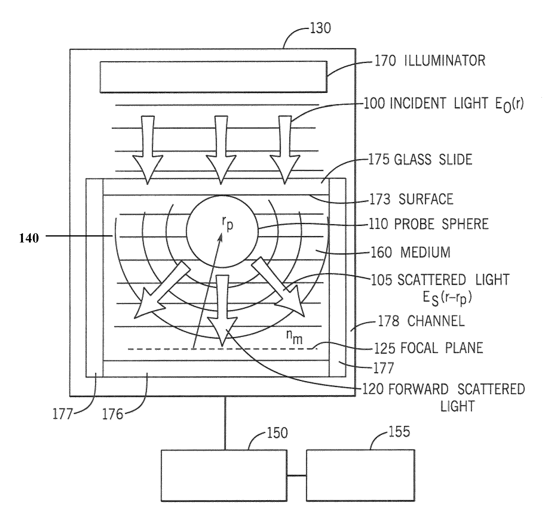
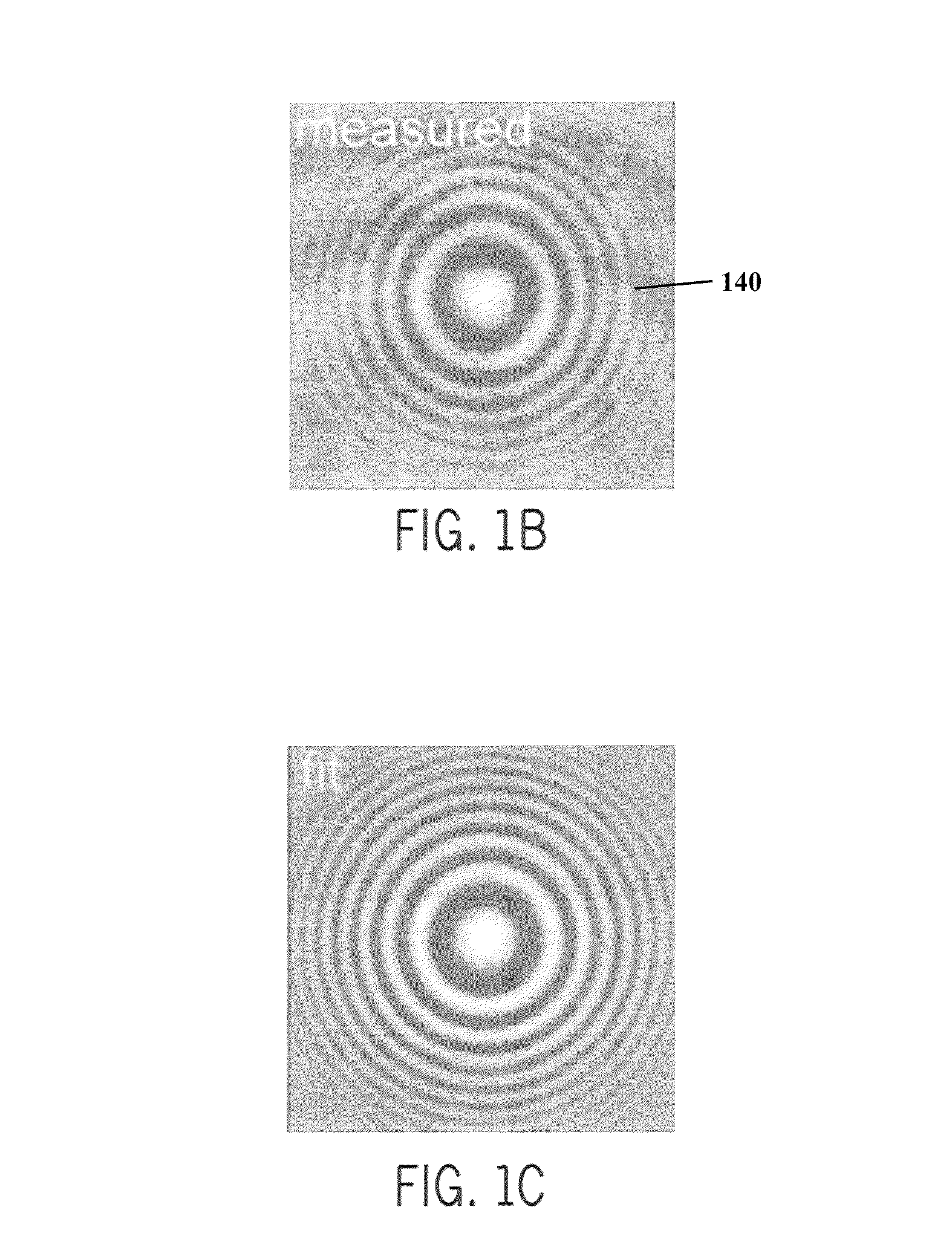
[0011]Our method and system is based on in-line holographic video microscopy, shown schematically in FIGS. 1A-1C, in which a refractive index probe 110 (e.g., a refractive index probe sphere) is illuminated with a collimated beam of coherent light 100. The light 105 scattered by the refractive index probe 110 (embedded in medium 160) and interferes with the unscattered portion 120 of the illumination in the focal plane 125 of an otherwise conventional optical microscope 130. The interference pattern 140 is magnified and its intensity is recorded with a video camera 150. A computer / memory system 155 having a non-transitory memory and computer read / writability media for executing computer software therein can be used to analyze the intensity data using appropriate computer software in the media. Such a system as the system 155 can be e.g., entirely or part of or include other components and can include various microprocessors RAM, ROM and drives or other external media and memory devi...


PUM

PropertyMeasurementUnit
refractive indexaaaaaaaaaa

Abstract

An in-line holographic microscope is used for measurements of micrometer-scale particles and associated suspending fluid medium containing the particles. The system yields heterodyne scattering patterns that may be interpreted with Lorenz-Mie theory to obtain precise time-resolved information on the refractive index of the suspending medium for determining chemical composition, concentrations and makeup thereof. This approach can perform spatially resolved refractometry with measurements on calibrated refractive index standards and monitor chemical concentration in a microfluidic channel. Using commercially available colloidal spheres as probe particles and a standard video camera for detection yields volumetric refractive index measurements with a resolution of 2×10⁻³ RIU for each probe particle in each holographic snapshot.

Description

CROSS-REFERENCE TO RELATED PATENT APPLICATIONS[0001]This application is a PCT National Phase application of PCT / US2013 / 027112, filed Feb. 21, 2013, which claims the benefit of U.S. Provisional Patent Application No. 61 / 634,211, filed Feb. 24, 2012 and U.S. Provisional Patent Application No. 61 / 604,309, filed Feb. 28, 2012, 2012. All applications are incorporated herein by reference in their entirety.GOVERNMENT RIGHTS[0002]This work was supported by the National Science Foundation through Award No. DMR-0922680 and the U.S. Government has certain rights in this invention. BACKGROUND OF THE INVENTION[0003]Optical probes are essential to many lab-on-a-chip systems which require precise time-resolved information on the refractive index of a fluid medium. Considerable effort, therefore, has been focused on developing techniques to measure the refractive index of picoliter samples using refractive index probes. One approach is to integrate a refractometer into the microfluidic device, ...

Claims


Application Information

Patent Timeline
Patent Type & Authority Patents(United States)
IPC IPC(8): G01N21/45G01N21/41G02B21/36G01N15/14G01N21/47
CPCG01N21/453G01N15/1429G01N15/1456G01N21/41G01N21/4133G02B21/361G01N2015/1454G01N2021/4707G01N2201/0612G01N2201/08G03H2001/0447G03H1/0443
Inventor SHPAISMAN, HAGAYKRISHNATREYA, BHASKAR JYOTIGRIER, DAVID G.
Owner NEW YORK UNIV
Learn More