
Needle biopsy device

a biopsy device and needle technology, applied in the field of needle biopsy devices, can solve the problems of cumbersome attachment of the device to the echoendoscope, numerous delays and failures, and significant procedures, and achieve the effects of enhancing echogenicity and ultrasonic visibility, reducing drag force, and increasing overall dimension of the needl

Active Publication Date: 2015-11-17
TYCO HEALTHCARE GRP LP
View PDF704 Cites 6 Cited by
  • Summary
  • Abstract
  • Description
  • Claims
  • Application Information

AI Technical Summary

Benefits of technology

This patent describes various improvements to a needle and sheath assembly used in ultrasonic imaging. These improvements include a tapered region on the needle to increase its stability, materials or design features to enhance echogenicity and ultrasonic visibility, and a stylet disposed within the needle. The needle housing member can also include an indentation for engaging with an adaptation member, and a strain relief member to reduce friction between the needle and sheath lumen. Overall, these improvements improve the performance of the needle and sheath assembly in ultrasonic imaging.

Problems solved by technology

First, the means of attaching a device to an echoendoscope is cumbersome. For example, these devices presently utilize male fitting adapters that must be screwed onto a female luer port of an endoscope.
Second, prior art devices provide sub-optimal ergonomics of use. More specifically, a clinician must actuate a number of handles independently and lock respective handles in position via cap screw arrangement to secure the device. The cumulative actions required by a clinician result in significantly drawn out procedures.
Third, needles commonly kink or deform during removal from a device causing numerous delays and failures.
Fourth, multiple passes per procedure are required, which prolong the procedure and result in a clinician needing to reconfirm the location of a needle relative to a desired aspiration site with each new pass.
Additionally, prior art devices are not designed to individually accommodate needles of various diameters.
As a result, instability in the ability of the needle to puncture a desired lesion or cyst can result causing increased manipulation time for the clinician and loss of procedural efficiency.
This interference may be a drag force creating frictional resistance between an outer diameter of the needle and an inner diameter of the sheath lumen.

Method used


Image

  • Needle biopsy device
  • Needle biopsy device
  • Needle biopsy device

Examples


Embodiment Construction

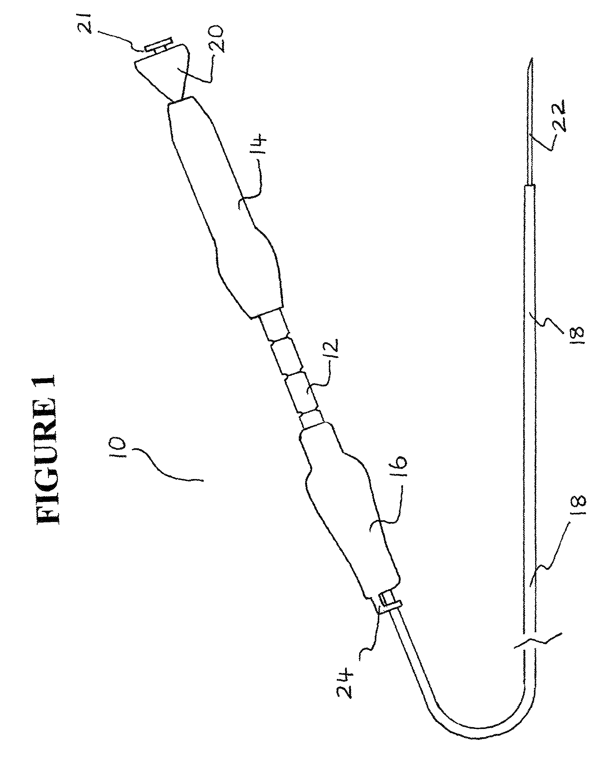
[0053]The exemplary embodiments of the needle biopsy device and methods of operation disclosed are discussed in terms of needle biopsy devices for collecting tissue, fluid, and cell samples from a body in conjunction with an endoscopic ultrasound or endoscopic bronchial ultrasound. It is envisioned that the present disclosure, however, finds application to a wide variety of biopsy devices for the collection of samples from a subject. It is also envisioned that the present disclosure may be employed for collection of body fluids including those employed during procedures relating to phlebotomy, digestive, intestinal, urinary, veterinary, etc. It is contemplated that the needle biopsy device may be utilized with other needle biopsy applications including, but not limited to, fluid collection, catheters, catheter introducers, spinal and epidural biopsy, aphaeresis, dialysis, etc.

[0054]In the discussion that follows, the term “proximal” refers to a portion of a structure that is closer ...


PUM


Abstract

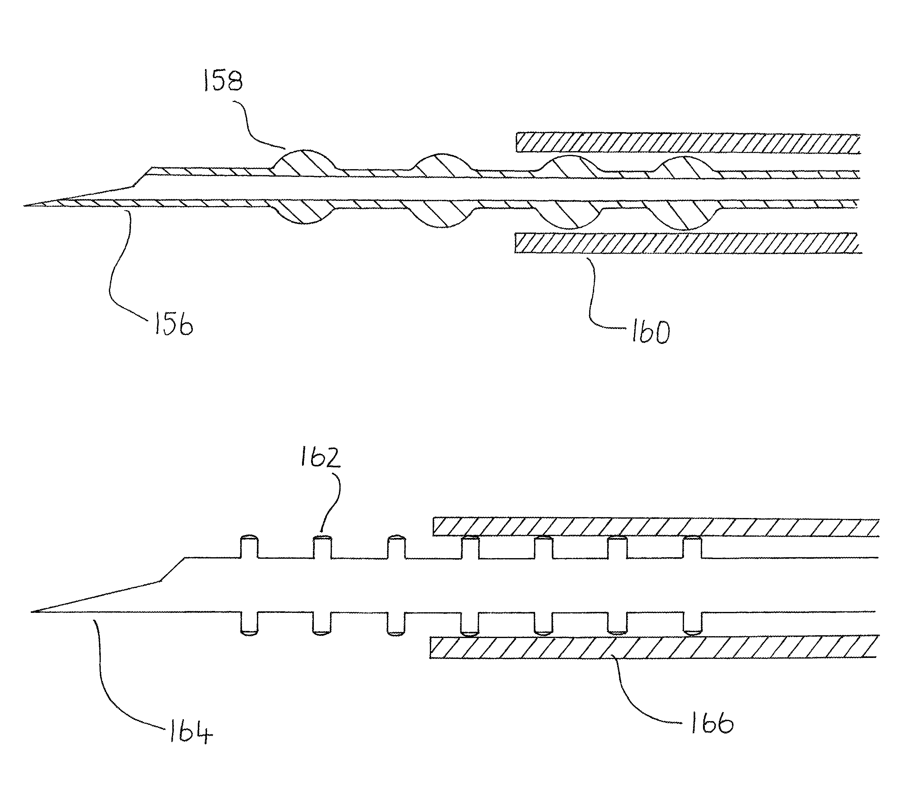
A device for needle biopsy is provided. The device includes a handle member having proximal and distal portions. A proximal handle member is disposed to the proximal portion of the handle member and a distal handle member is disposed to the distal portion of the handle member. A sheath lumen is disposed within the handle member and extends from the distal portion of the handle member. A needle housing member is partially disposed to the proximal portion of the handle member and a needle is disposed within the sheath lumen. A plurality of protrusions are disposed upon the needle.

Description

BACKGROUND[0001]1. Technical Field[0002]The present disclosure generally relates to the biopsy devices, and more particularly, needle biopsy devices for collecting tissue, fluid, and cell samples in conjunction with procedures such as endoscopic ultrasound or endoscopic bronchial ultrasound.[0003]2. Background of the Invention[0004]Endoscopic ultrasounds have been used for more than twenty five years within the field of medicine. These procedures allow clinicians to scan, locate and identify individual layers of the gastrointestinal (GI) tract and determine the location of individual mucosal and submucosal layers. As a result, appropriate therapeutic modes of treatment for malignancies and various abnormalities may be determined.[0005]An endoscopic ultrasound procedure consist of several steps. First, a clinician sedates a patient and inserts a probe via esophagogastroduodenoscopy into the patient's stomach and duodenum. Second, an endoscope is passed through the patient's mouth and...

Claims


Application Information

Patent Timeline
Patent Type & Authority Patents(United States)
IPC IPC(8): A61B10/00A61B10/04A61B10/02A61B17/00A61B17/34A61B19/00
CPCA61B10/04A61B10/0283A61B2017/00424A61B2017/3413A61B2019/4805A61B2019/5425A61B10/0233A61B90/39A61B2010/045A61B2090/0801A61B2090/3925
Inventor MUGAN, JOHNMURPHY, BRIANMCWEENEY, JOHN
Owner TYCO HEALTHCARE GRP LP
Learn More