Eureka AIR delivers breakthrough ideas for toughest innovation challenges, trusted by R&D personnel around the world.

Configurable pulse amplitude modulation clock data recovery

a pulse amplitude modulation and clock data technology, applied in the direction of digital transmission, synchronisation error correction, electrical equipment, etc., can solve the problems of higher frequency operation, higher power consumption, and even more attractive serdes circuits, so as to facilitate dual-mode signaling, reduce workload, and operate at higher frequencies.

Active Publication Date: 2015-11-10
ORACLE INT CORP
View PDF9 Cites 23 Cited by
  • Summary
  • Abstract
  • Description
  • Claims
  • Application Information

AI Technical Summary

Benefits of technology

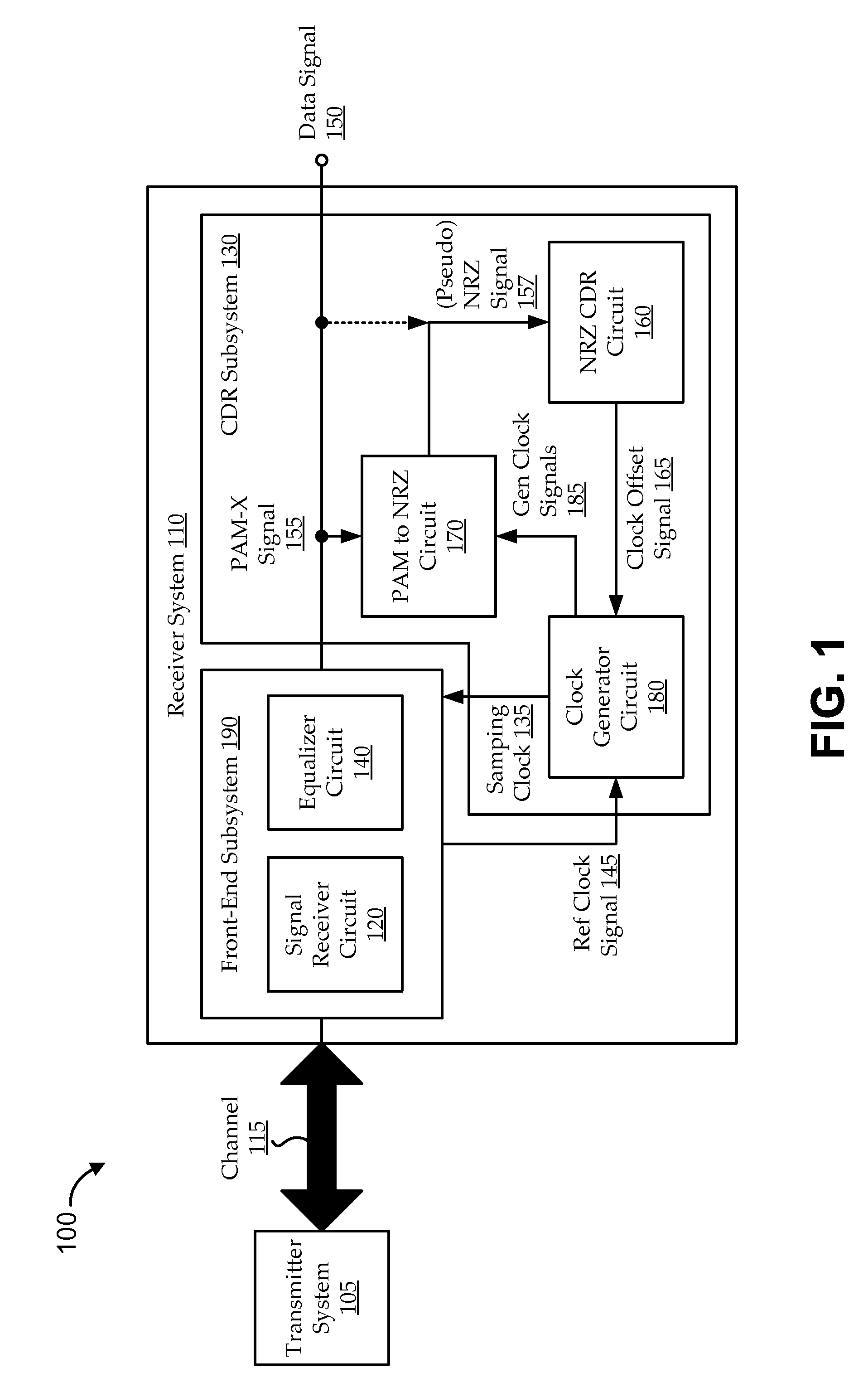
The patent describes a system and method for using a new signaling technology called PAM-X to improve the performance of high-speed digital communication. The system includes a circuit that samples the data signal over time and calculates the apparent direction of signal transition, which is then used to determine the offset of the clock signal. This offset is then used to generate a more accurate clock signal for the receiver. The system can operate at different frequencies and can use both standard NRZ signaling and novel, pseudo-NRZ signaling derived from PAM-X signaling. The technical effects of this technology include improved data transmission speed and reduced latency, as well as improved reliability and stability.

Problems solved by technology

As bus speeds increase, parallel communications manifest even higher power consumption and more issues relating to timing (e.g., skew mismatches and bit misalignment), making SERDES circuits even more attractive.
This can involve determining where signal transitions (e.g., zero-crossings) occur, which can often be frustrated by clock jitter, noisy data, small signal levels, and / or other difficult conditions.
Higher frequency operation can manifest other issues, as well.
Another issue is that clock generating circuits, which are often some of the most power-hungry portions of such circuit systems, tend to consume even more power at higher frequencies.

Method used


Image

  • Configurable pulse amplitude modulation clock data recovery
  • Configurable pulse amplitude modulation clock data recovery
  • Configurable pulse amplitude modulation clock data recovery

Examples


Embodiment Construction

[0017]Many electronics applications include communications channels that have transmitter and receiver components to move data through the electronics application. Some receiver circuits are serializer / deserializer (SERDES) receiver circuits that can, for example, convert parallel data from the communications channel into a serial data stream for processing, etc. Various functions of the SERDES rely on clocking to effectively sample and / or process the data being received from the channel, and the clock signal is often recovered from the data itself using a clock data recovery (CDR) circuit. Some CDR circuits (e.g., Mueller-Muller (MM) CDRs) use data samples to recover clock timing information. Thus, the rate of the resulting clock signal is the data rate, and such CDR techniques are often referred to as “at-rate” CDRs. At-rate CDR techniques provide various features, such as avoiding double-rate clocking, which can appreciably reduce power consumption.

[0018]Still, while serial commu...


PUM


Abstract

Embodiments include systems and methods for using generalized pulse amplitude modulation (PAM-X) signaling with an at-rate not-return-to-zero (NRZ) clock data recovery (CDR) system. Some implementations include dual-mode signaling for an at-rate CDR (e.g., using standard NRZ signaling at lower operating frequencies and pseudo-NRZ signaling derived from PAM-X signaling at higher operating frequencies. Embodiments derive an apparent direction of signal transition from PAM-X signaling. The direction can be used to calculate pseudo-NRZ values. For example, when the PAM-X signal transitions in an upward direction, a pseudo-current NRZ value and a pseudo-previous NRZ value of ‘−1’ and ‘+1’ can be generated, respectively. An at-rate NRZ CDR can use the pseudo-NRZ values and a derived error value to make an offset determination. The offset determination can then be used to offset a generated clock signal in the CDR system.

Description

FIELD[0001]Embodiments relate generally to clock data recovery circuits, and, more particularly, to techniques for error signal translation for configurable pulse amplitude modulation (PAM) clock data recovery circuits.BACKGROUND[0002]As the demand continues to increase for high-speed computing applications, such applications often rely on increasing efficiency in both the energy and bandwidth of communications links. For example, serializer / deserializer (SERDES) circuits are becoming ubiquitous in many computational environments. The SERDES can compress a relatively wide, parallel input into a relatively narrow, serial signal (e.g., a single “bit,” differential signal) for communication over a serial bus. The serial bus switches at an appreciably higher rate than the parallel bus, and serial communication of the data stream tends to reduce cost, complexity, power, and board real estate relative to comparable parallel communications. As bus speeds increase, parallel communications m...

Claims


Application Information

Patent Timeline
IPC IPC(8): H04L7/00
CPCH04L7/0016H04L7/0062H04L7/0334H04L7/0087H04L7/0058
Inventor MIN, JIHONGHUANG, DAWEISU, JIANGHUIZHANG, HONGTAO
Owner ORACLE INT CORP
Why Eureka
Eureka Blog
Learn More