Organic electroluminescent element and lighting device
an electroluminescent element and lighting device technology, applied in the direction of triarylamine dyes, perylene derivatives, anthracene dyes, etc., can solve the problems of poor flatness of the interface between the light-extraction layer and the transparent electrode, and the light trapped in the device cannot be extracted, so as to achieve high light-extraction efficiency and high luminance
- Summary
- Abstract
- Description
- Claims
- Application Information
AI Technical Summary
Benefits of technology
Problems solved by technology
Method used
Image
Examples
first exemplary embodiment
[0093]A first exemplary embodiment of the invention will be described below with reference to the attached drawings.
Organic Electroluminescence Device
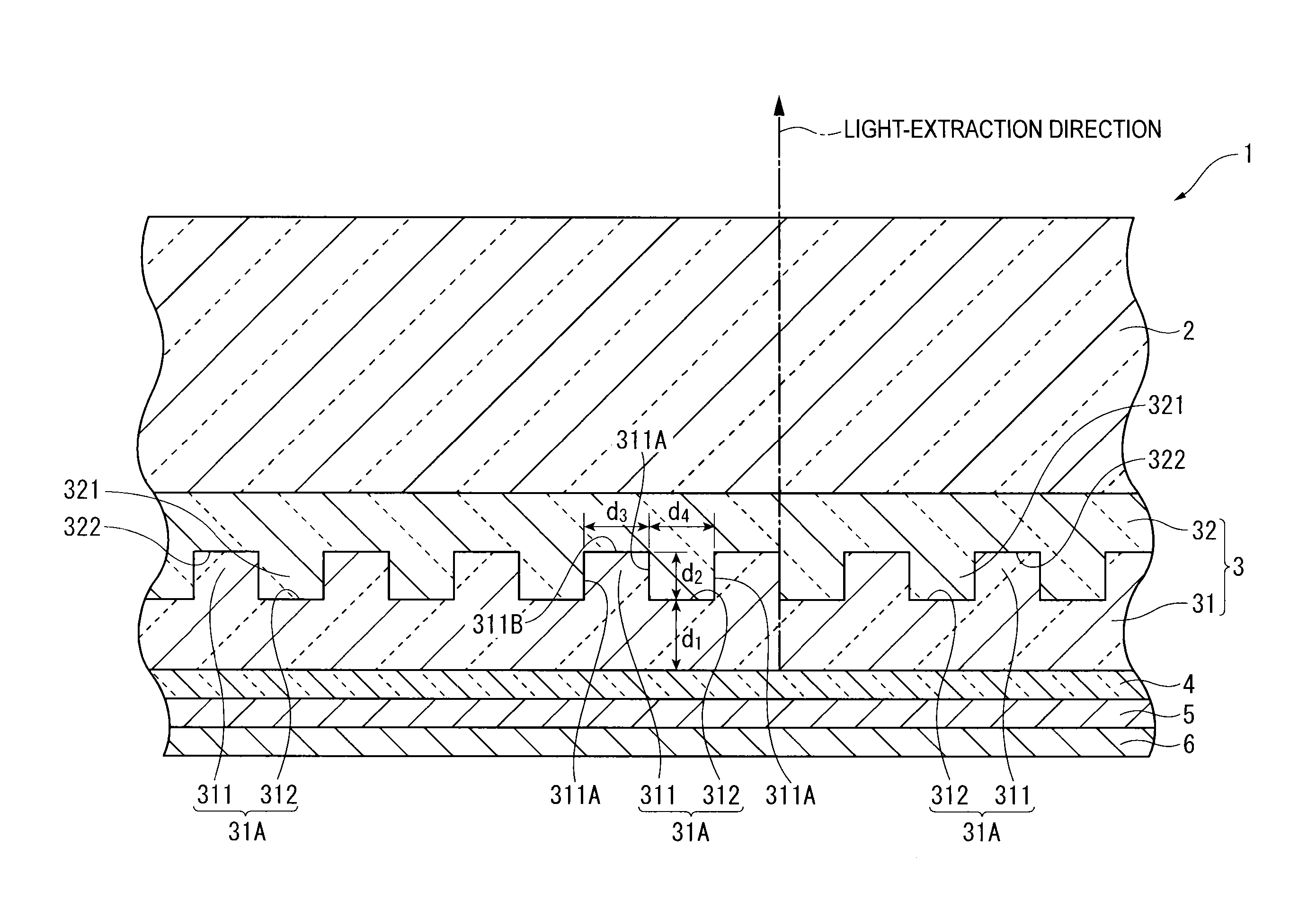
[0094]FIG. 4 is a cross section in a thickness direction of an organic electroluminescence device (referred to as organic EL device hereinafter) according to a first exemplary embodiment of the invention, where a part of the cross section is enlarged.
[0095]The organic EL device 1 is provided by laminating a light-transmissive substrate 2, a light-extraction layer 3, a transparent electrode 4, an organic emitting layer 5 and an opposing electrode 6 in this sequence.
Light-Transmissive Substrate
[0096]The light-transmissive substrate 2 is a flat smooth plate member for supporting the light-extraction layer 3, the transparent electrode 4, the organic emitting layer 5 and the opposing electrode 6. The organic EL device 1 is a so-called bottom-emission device in which the radiation light generated in the organic emitting layer 5 is extracted ...
second exemplary embodiment
[0139]Next, a second exemplary embodiment of the invention will be described below with reference to the attached drawings.
Organic Electroluminescence Device
[0140]FIG. 7 is a cross section in a thickness direction of an organic EL device 40 according to the second exemplary embodiment of the invention, where a part of the cross section is enlarged.
[0141]The organic EL device 40 according to the second exemplary embodiment has a structure similar to that of the organic EL device 1 according to the first exemplary embodiment except for an electron transporting zone 41 provided between the organic emitting layer 5 and the opposing electrode 6 of the organic EL device 1 and a hole transporting zone 42 provided between the organic emitting layer 5 and the transparent electrode 4. Specifically, the organic EL device 40 is provided by laminating the light-transmissive substrate 2, the light-extraction layer 3, the transparent electrode 4, the hole transporting zone 42, the organic emitting...
third exemplary embodiment
[0165]Next, a third exemplary embodiment of the invention will be described below with reference to the attached drawings.
Organic EL Device
[0166]FIG. 10 is a cross section in a thickness direction of an organic EL device 50 according to the third exemplary embodiment of the invention, where a part of the cross section is enlarged.
[0167]The organic EL device 50 according to the third exemplary embodiment has a structure similar to that of the organic EL device 40 according to the second exemplary embodiment except for an intermediate unit 5A provided between the electron transporting zone 41 and the transparent electrode 4 of the organic EL device 40 and a plurality of organic emitting layers 51, 55 and 56 sandwiching the intermediate unit 5A. Specifically, the organic EL device 50 is provided by laminating the light-transmissive substrate 2, the light-extraction layer 3, the transparent electrode 4, the hole transporting zone 42, the first organic emitting layer 51, the intermediate...
PUM
| Property | Measurement | Unit |
|---|---|---|
| width d3 | aaaaa | aaaaa |
| width d3 | aaaaa | aaaaa |
| thickness | aaaaa | aaaaa |
Abstract
Description
Claims
Application Information
 - R&D
- Intellectual Property
- Life Sciences
- Materials
- Tech Scout
- Unparalleled Data Quality
- Higher Quality Content
- 60% Fewer Hallucinations
Browse by: Latest US Patents, China's latest patents, Technical Efficacy Thesaurus, Application Domain, Technology Topic, Popular Technical Reports.
© 2025 PatSnap. All rights reserved.Legal|Privacy policy|Modern Slavery Act Transparency Statement|Sitemap|About US| Contact US: help@patsnap.com


