
Practical autonomous seismic recorder implementation and use

a technology of autonomous recording and recording device, which is applied in the field of methods and apparatus for generating seismic signals, can solve the problems of not using or providing a conventional digital timer or clock that achieves accuracy, and none currently using multiple gps systems, so as to achieve sufficient accuracy, reduce the size of the autonomous recording device, and reduce the cost

Active Publication Date: 2015-11-03
CONOCOPHILLIPS CO
View PDF28 Cites 2 Cited by
  • Summary
  • Abstract
  • Description
  • Claims
  • Application Information

AI Technical Summary

Benefits of technology

[0016]Prior studies have used the HFVS concept combining unique sweep encoding of ZENSEIS™ and timing synchronization to coordinate source and data recorders. There are multiple methods described in previous studies for the extraction of seismic data for a single seismic record without synchronizing the boxes (distributed recorders), and although each must maintain absolute time, they do not describe the use of multiple distributed GPS units or the use field timers as a method of synchronizing time and seismic signals. None currently use or provide a conventional digital timer or clock that achieves the accuracy required to synchronize seismic sources and data recorders automatically to achieve an autonomous data recorder. None currently use multiple GPS systems located at each recorder and source to confirm and synchronize timing across the entire system. By combining the timing accuracy of a GPS with an inexpensive timer or clock, the size of the autonomous data recorder can be dramatically reduced and less energy is required to maintain the system. Because the system has both an accurate near microsecond timing system and inexpensive timer, the system has sufficient accuracy for an HFVS, ZENSEIS™, slipsweep or similar high fidelity seismic survey, yet can overcome gaps in communication and radio signal without compromising the data recorded therein. The use of a “field timer” reduces battery use but allows sufficient accuracy for simultaneous and continuous seismic surveys over extended periods of time with the autonomous seismic recorder.
[0032]Finally, data recorders may be set to record both data points and field time points over a given period. In one example, the data recorder records field time every 1000th data point. Inversely, the field timer may transmit a time stamp every second. If the data recorder and the field timer are synchronized, each field time point should be synchronized at an exact data / time interval. Thus at 1000 datapoints per second, each field time mark should be exactly 1 second apart. Drift in the field timer or drift in the data record will be easily identified and corrected. The data / field time can be corrected by correcting the field time, correcting the data record, or using inversion as described in U.S. Ser. No. 61 / 109,279 to separate and synchronize separated source-receiver centerpoint data.
[0034]Seismic energy sources include ZENSEIS™, vibroseis, seismic vibrator, airgun, plasma shot, and / or dynamite. Seismic recording systems include autonomous data recorders with data receivers, i.e. geophone, hydrophone, accelerometer, electrodynamic receiver, and may include GPS satellite receivers. The control timer and field timer can be mechanical timers, electromechanical timers, digital timers, and / or software timers. Although there can be more than one type of control and field timer, they must each have at least one identical timer to monitor changes in drift. The standard timer can be accurately measured using an oscillator, GPS time record, radio time standard, “Coordinated Universal Time” (UTC), and binary coded decimal (BCD) time code.

Problems solved by technology

There are multiple methods described in previous studies for the extraction of seismic data for a single seismic record without synchronizing the boxes (distributed recorders), and although each must maintain absolute time, they do not describe the use of multiple distributed GPS units or the use field timers as a method of synchronizing time and seismic signals.
None currently use or provide a conventional digital timer or clock that achieves the accuracy required to synchronize seismic sources and data recorders automatically to achieve an autonomous data recorder.
None currently use multiple GPS systems located at each recorder and source to confirm and synchronize timing across the entire system.

Method used


Image

  • Practical autonomous seismic recorder implementation and use
  • Practical autonomous seismic recorder implementation and use
  • Practical autonomous seismic recorder implementation and use

Examples


example 1

Simple Autonomous Recorder

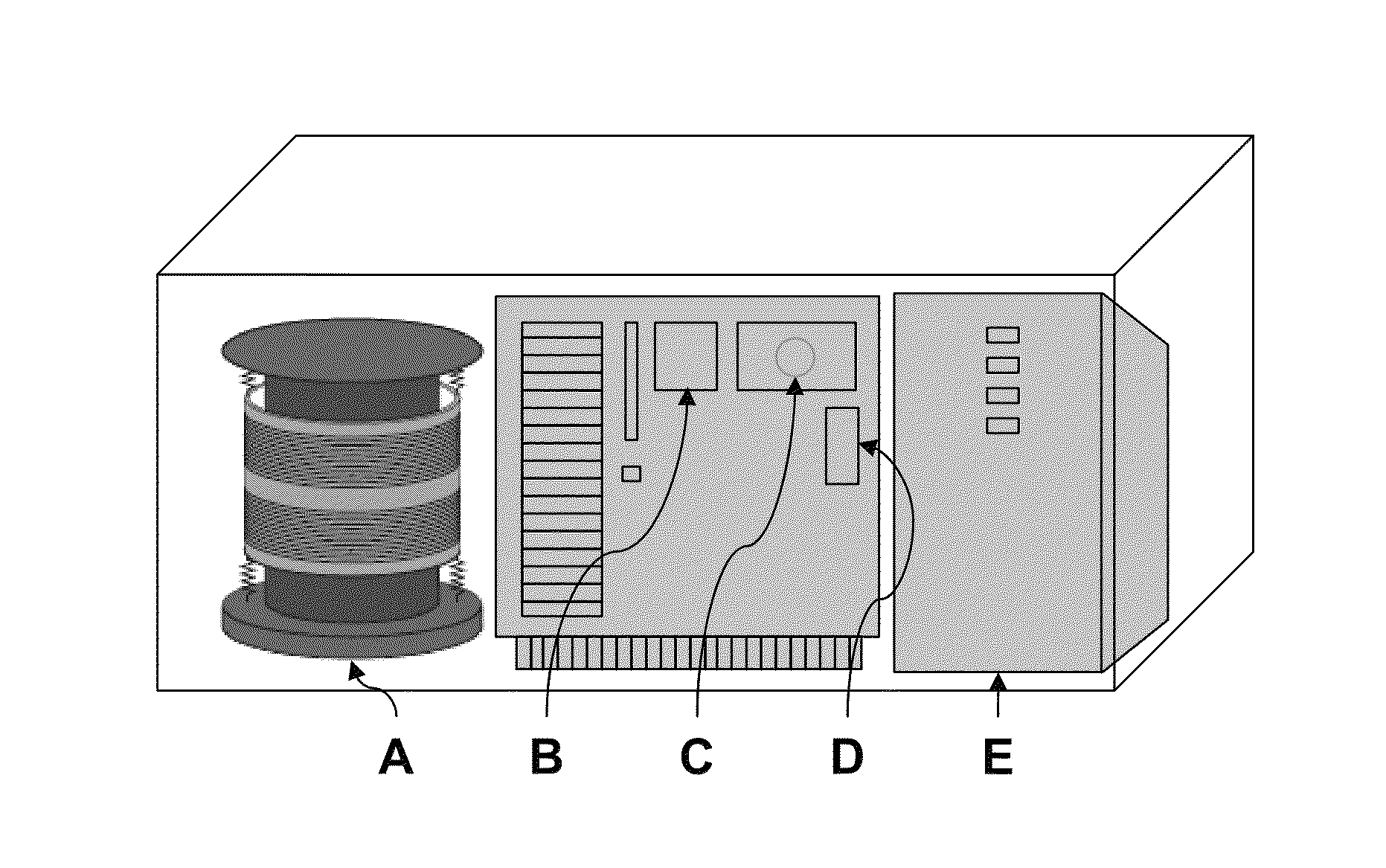
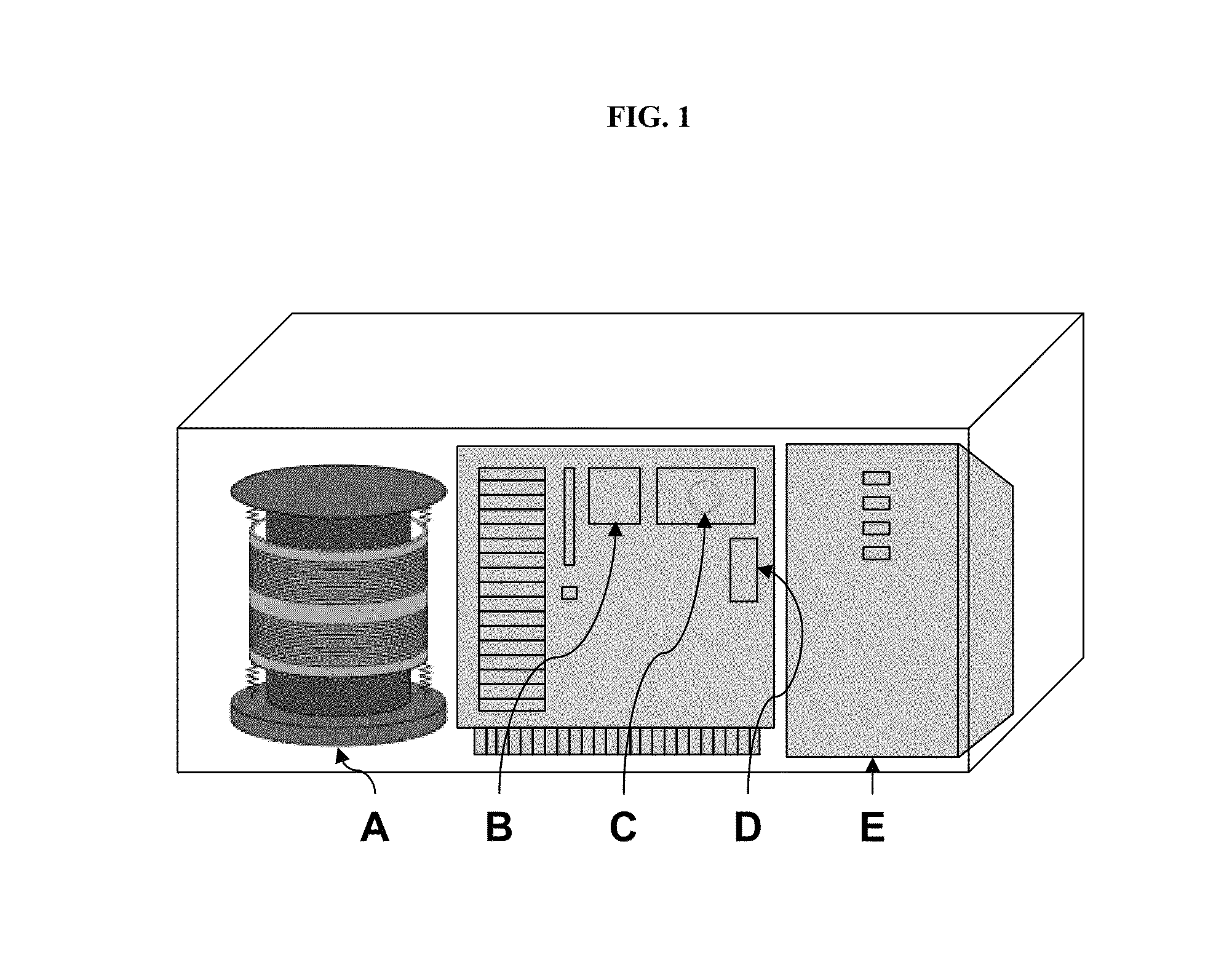
[0059]As shown in FIG. 1, an autonomous recorder is provided that contains a seismic receiver (A), a field timer (B), a processor (C), a data transmitter (D), and a battery (E). The autonomous recorder as diagrammed in FIG. 4 simply transmits a seismic signal and field time record directly to a separate, remote recorder where the seismic data and time are recorded along with data from other recorders. The field timer may be a separate timer or a computer counter incorporated into the processor.

example 2

GPS Synchronized Autonomous Recorder

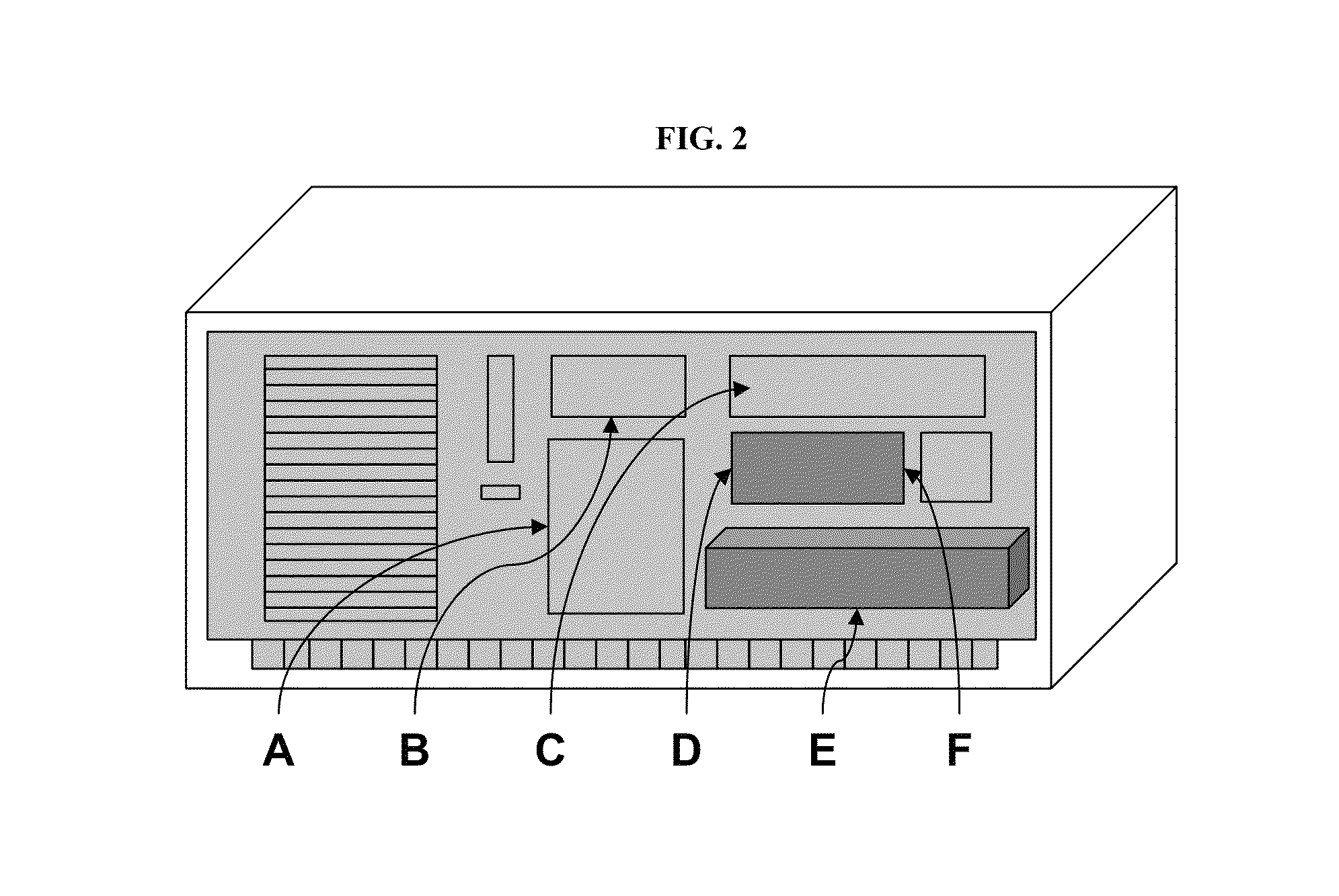
[0060]As shown in FIG. 2, an autonomous recorder is provided that contains a seismic receiver (A), a field timer (B), a processor (C), a data transmitter (D), a battery (E) and a GPS unit (F). The autonomous recorder as diagrammed in FIG. 4 transmits a seismic signal and field time record directly to a separate, remote recorder where the seismic data and time are recorded along with data from other recorders. The GPS signal is transmitted upon request, at defined times to the central recorder.

example 3

Buffered Autonomous Recorder

[0061]As shown in FIG. 3, an autonomous recorder is provided that contains a seismic receiver (A), a field timer (B), a processor (C), a data transmitter (D), a battery (E) and a GPS unit (F). The autonomous recorder may contain a geophone, accelerometer, directional 3-way accelerometer, one or more solar panels, a GPS processor with built in computer based timer, a memory buffer and transmitter. The autonomous recorder as shown in FIG. 3 stores seismic, timer, and GPS data in a buffer memory. The data is transmitted during and after a seismic survey when the central recorder requests the stored data or at specific time intervals. This system may have multiple redundant components to monitor timing drift, provide a “sleep battery,” multiple processors, multiple transmitters, and other systems required for operation of individual components or the system as a whole.

[0062]In one embodiment the autonomous recorder has a central processor, a GPS, multidirecti...


PUM


Abstract

Seismic systems and methods are provided to synchronize both source and receiver data using inexpensive timers and / or low energy timers to obtain high resolution seismic data.

Description

PRIOR RELATED APPLICATIONS[0001]This application is a non-provisional application which claims benefit under 35 USC §119(e) to U.S. Provisional Application Ser. No. 61 / 112,875 filed Nov. 10, 2008, entitled “PRACTICAL AUTONOMOUS SEISMIC RECORDER IMPLEMENTATION AND USE,” which is incorporated herein in its entirety.FIELD OF THE DISCLOSURE[0002]The present disclosure generally relates to methods and apparatus for generating seismic signals, and particularly to methods of synchronizing at the source, receiver, and central recorder during seismic data acquisition.BACKGROUND OF THE DISCLOSURE[0003]Seismic surveys image or map the subsurface of the earth by imparting acoustic energy into the ground and recording the reflected energy or “echoes” that return from the rock layers below. The source of the acoustic energy can be generated by explosions, air guns vibrators, and the like. The energy source is positioned on or near the surface of the earth. Each time the energy source is activated...

Claims


Application Information

Patent Timeline
Patent Type & Authority Patents(United States)
IPC IPC(8): G01V1/36G01V1/20G01V1/24
CPCG01V1/24G01V1/20G01V2200/12
Inventor EICK, PETER M.BREWER, JOEL D.
Owner CONOCOPHILLIPS CO
Learn More