
Data alignment in large scale electrical system applications

a technology for electrical systems and data alignment, applied in the field of automatic precision alignment of data, can solve problems such as problems such as problems such as problems such as inaccurate data alignment from frequency modulation alignment algorithms, and achieve the effect of improving data alignment approaches and reducing the number of cycle count offset errors

Active Publication Date: 2015-11-03
SCHNEIDER ELECTRIC USA INC
View PDF23 Cites 4 Cited by
  • Summary
  • Abstract
  • Description
  • Claims
  • Application Information

AI Technical Summary

Benefits of technology

This approach ensures precise data alignment across large electrical systems, reducing errors and enabling accurate sequence analysis, fault detection, and power flow determination by synchronizing data with a common reference point.

Problems solved by technology

Because of the magnitude and complexity of such electrical systems, accurate data alignment from frequency modulation alignment algorithms may be problematic due to the inherent phase shift of the voltage signal.

Method used


Image

  • Data alignment in large scale electrical system applications
  • Data alignment in large scale electrical system applications
  • Data alignment in large scale electrical system applications

Examples


Embodiment Construction

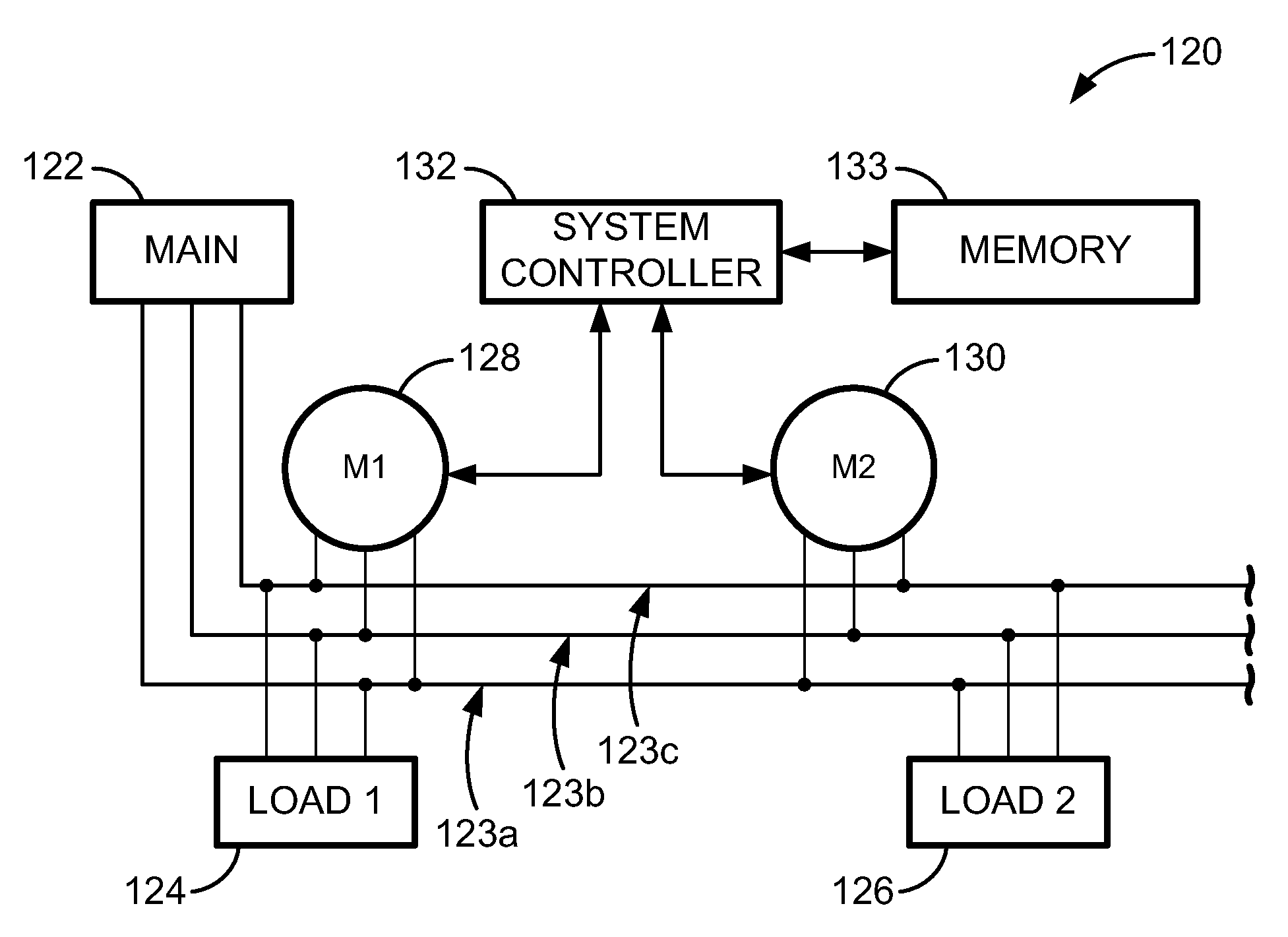
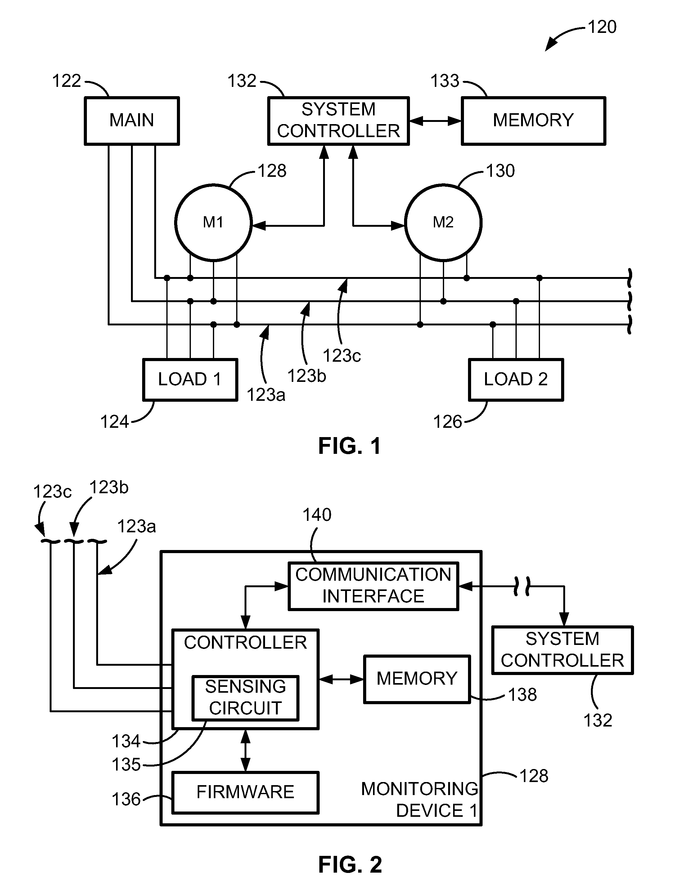
[0032]FIG. 1 illustrates a simplified configuration of a power monitoring system 120. The power monitoring system 120 includes a main 122 connected to a first load 124 and to a second load 126. A reference monitoring device 128 and a second monitoring device 130 measure electrical characteristics or parameters associated with the power delivered to the first load 124 and the second load 126, respectively. Each monitoring device (128, 130) is communicatively coupled to a system controller 132. In a configuration, the system controller 132 can be a computer. The reference monitoring device 128 is alternately referred to herein as a first monitoring device. The measured electrical characteristics can include current or voltage, for example.

[0033]The reference monitoring device 128 is connected to the second monitoring device 130 by a first conductor 123a, a second conductor 123b, and a third conductor 123c. The conductors (123a, 123b, 123c) can be line conductors used to carry three di...


PUM


Abstract

A method for automatically aligning measured power-related data in a power monitoring system to a common reference point. A conductor in a power delivery system is modeled according to an equivalent pi model of a transmission line that is characterized by model parameters. The conductor is monitored on both ends by a reference monitoring device and a second monitoring device. The voltage and current are measured in either the reference monitoring device or the second monitoring device and a phase shift offset between the voltages or currents at the two devices is calculated. The calculated phase shift offset corresponds to a temporal delay between events observed at the pair of devices, and calculating and storing the phase shift offset allows a power monitoring system controller to more accurately align data received from monitoring devices.

Description

FIELD OF THE INVENTION[0001]The present invention relates generally to utility monitoring systems, and, in particular, to automated precision alignment of data using variations in the fundamental frequency and phase shift offsets between monitoring devices.BACKGROUND[0002]U.S. Pat. No. 7,684,441 generally discloses techniques for aligning measured data by analyzing the grid's frequency or amplitude variations to generate a cycle count offset by which one monitoring device's data lags or leads a reference monitoring device's data. This approach works very well for radial-fed power systems. However, power systems that include apparatuses such as transformers or very long conductor lengths such as transmission lines can introduce phase shifts into the measured data between monitoring devices upstream and downstream of the transformers or generators. These small phase shifts introduce fractional offsets in the cycle counts that can cause the cycle count offset to be shifted by fractions...

Claims


Application Information

Patent Timeline
Patent Type & Authority Patents(United States)
IPC IPC(8): G01R21/133H02J13/00
CPCG01R21/133H02J13/0006H02J13/00002Y04S10/30Y02E60/00
Inventor BICKEL, JON A.
Owner SCHNEIDER ELECTRIC USA INC
Learn More