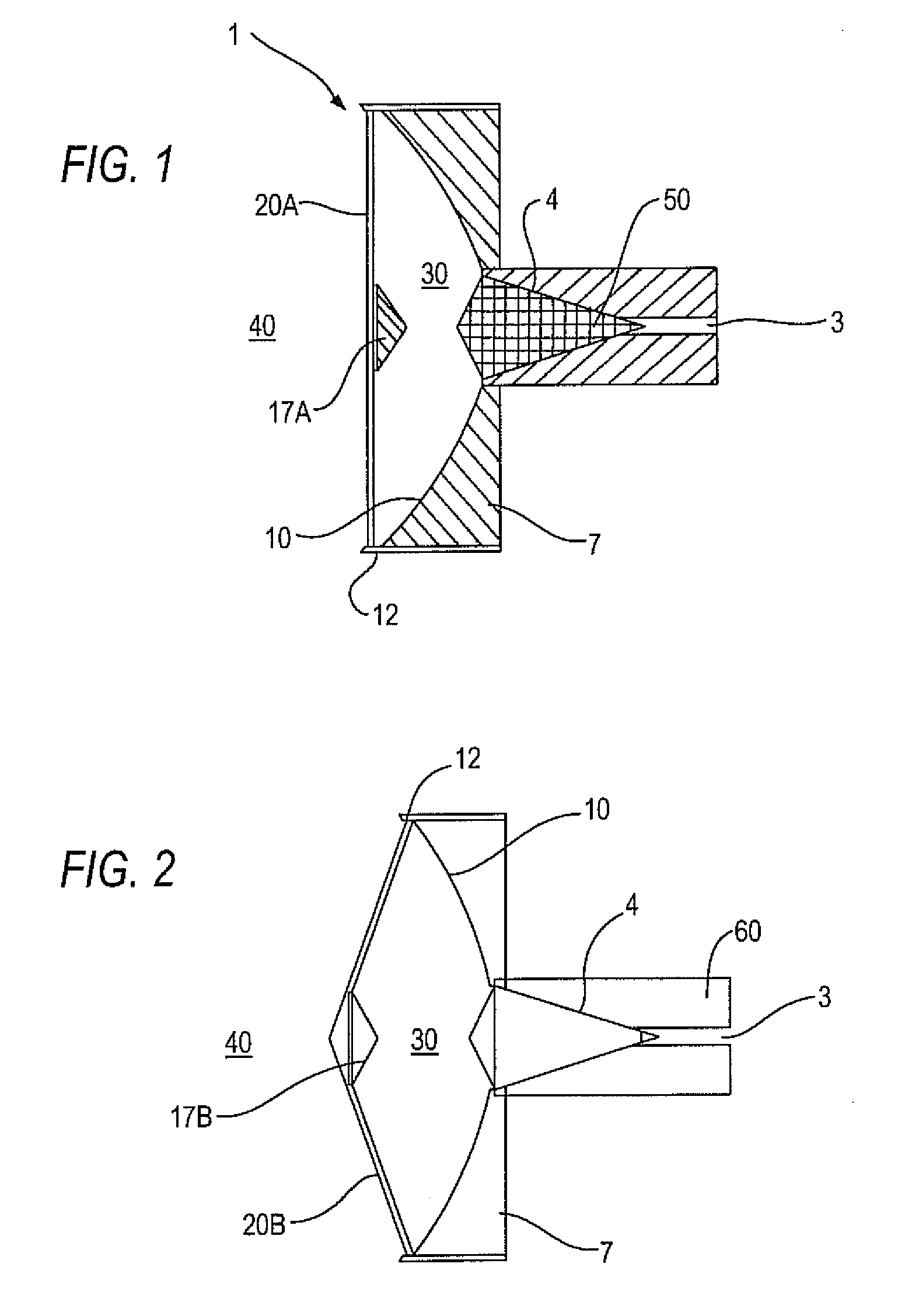
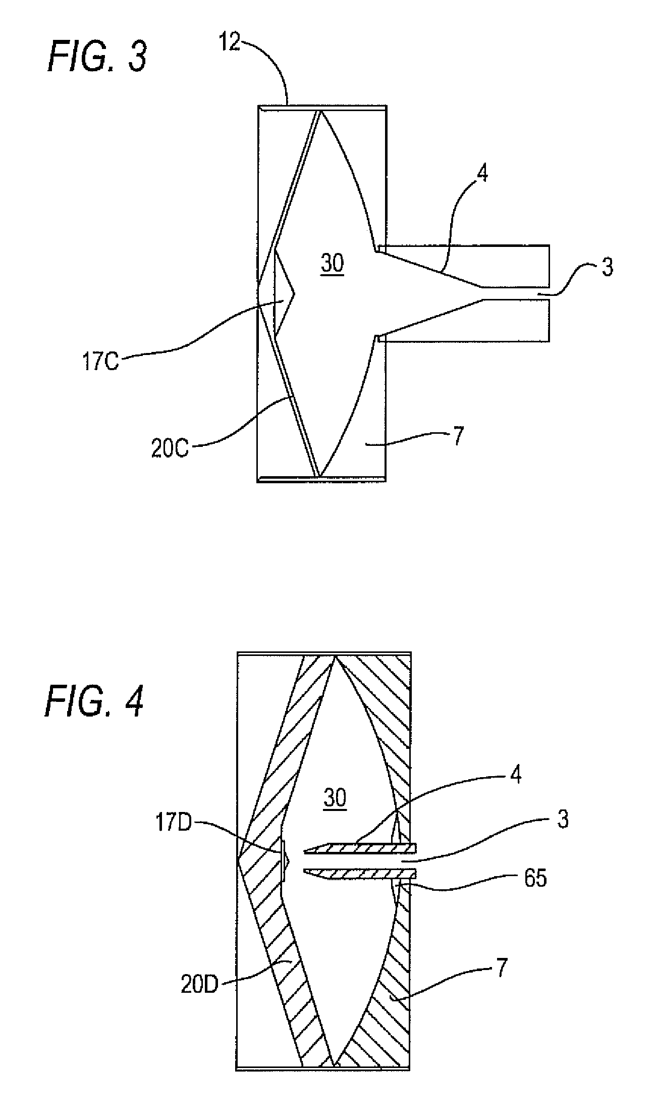
[0014]According to one aspect of the present invention, a sensor for a fill level measuring device for determining the fill level in a container by determining the delay time of high-frequency signals comprises a main reflector having an edge region and an interior region, a sub reflector, which is connected to the edge region of the main reflector via a radome, an inner space, which is encompassed by the radome and the main reflector, and a hollow waveguide which is connected to the main reflector and has a front end, which is oriented toward the sub reflector for coupling electromagnetic waves in and / or out. The radome can be connected to the sub reflector via adhesive bonding or screws. Preferably, however, the radome is provided and embodied as integral with, or unitary, or monolithic with the sub reflector. Consequently, the previously customary attachment of the sub reflector can be dispensed with. And as a result, the active antenna surface is enlarged, and the efficiency of the radiated power is increased, since the antenna array of the detector can no longer be interfered with by projecting connectors. This advantage has an impact particularly at higher frequencies, for example, in the range between 77 and 81 GHz, that is, in a range in which the retaining connectors or other attachments become quite large in proportion to the wavelength.
[0015]The sub reflector and the radome are preferably made of a first dielectric material, wherein the part of the dielectric material that forms the sub reflector has a reflective coating, preferably a metal coating, on its side that faces the inner space. This allows the radome and the sub reflector to be produced together in a simple process, and allows a modular structure for the sensor. The space inside the sensor is preferably sealed, pressure-tight and / or vacuum-tight, in relation to an outer space that surrounds the sensor, so that corrosive vapors from liquids, the fill level of which is to be determined, cannot damage the sensor, and bulk material cannot soil the sensor.
[0016]The edge region of the main reflector can be embodied as a collar which encompasses the inner region, and which is preferably embodied as a tubular collar that encompasses the inner region and projects in the direction of radiation. The beam direction of the sensor can thereby be improved. The radome can also have a collar that is embodied such that the radome can be screwed onto, screwed into, or operatively fit onto the collar of the main reflector in a positive and operative connection. For this purpose, the collar of the main reflector can have a corresponding threading, onto which the radome can be screwed, or into which the radome can be screwed. A secure mounting of the radome onto the main reflector can thereby be guaranteed.
[0018]The main reflector of the sensor can be embodied as parabolic or paraboloid, and it can either be made of a metal or can have a metal coating on the inner region of its side that faces the inner space. High efficacy of the radiated power can thereby be achieved. The sub reflector can be elliptical or hyperbolic in shape. It conducts the power radiated from the hollow waveguide to the main reflector and thereby ensures the desired radiation. Advantageously, the sensor is embodied as a Cassegrain antenna or as a Gregory antenna, and it is understood that those of skill in the particular art will recognize these phrases as being fully enabling based upon the skill in the art. The sub reflector can be embodied as concave according to the Gregory principle, or it can be embodied as convex according to the Cassegrain principle.
[0019]To increase mechanical stability, the radome is advantageously embodied as convex and / or conical, but is not limited to these sole geometric shapes. The radome can be made of a plastic, for example, but may be pursued of any other operatively advantageous material. Advantageously, it is made of polypropylene (PP) or polytetrafluoroethylene (PTFE). These materials are characterized by a dielectric constant that is suitable for the W-band range, and absorb the transmitted radiation only weakly. On the other hand, however, the materials are not entirely optimal with respect to temperature resistance and expansion, and therefore can be used only conditionally for determining fill level, for example, in pressure less or low-pressure applications and / or at temperatures that are not excessively high. In environments in which the sensor is exposed to high pressures, or in environments in which it must have a particularly high stability, the radome is advantageously made of a glass fiber reinforced plastic or a high-performance plastic. Materials that are particularly suitable as plastic materials in these cases include polyetherether ketone (PEEK) and polyether imides (PEI).
[0020]In one further adaptive and advantageous embodiment, the thickness of the radome is such that it corresponds to a whole-number multiple of half the dielectric wavelength of a coupled-in electromagnetic wave, wherein the wavelength preferably corresponds to a wavelength of the W-band, particularly preferably to a wavelength of between 77 GHz and 81 GHz. Interfering reflections back to the surfaces of the radome are thereby avoided.