Knee protection airbag apparatus

a knee protection and airbag technology, applied in the direction of vehicular safety arrangments, pedestrian/occupant safety arrangements, vehicle components, etc., can solve the problems of insufficient connection between the ceiling wall portion and the general portion, damage to the connection portion, and the inability to form the rear surface-side of the general portion for the deployment and inflation of the airbag, so as to reduce the occupancy space of the upper panel portion, improve the appearance of the vicinity, and reduce the gap

Active Publication Date: 2015-10-20
TOYODA GOSEI CO LTD
View PDF13 Cites 2 Cited by
  • Summary
  • Abstract
  • Description
  • Claims
  • Application Information

AI Technical Summary

Benefits of technology

[0009]The present invention is intended to solve the above-mentioned problems. An object of the present invention is to provide a knee protection airbag apparatus that can stably form a space for deployment and inflation of an airbag in front of the knees of an occupant.
[0013]In the knee protection airbag apparatus of the present invention, the vicinity of the fixation portion of the upper portion of the general portion functions as the bending deformation portion. The ceiling wall portion, which is the lower portion of the upper panel portion, and the general portion, which is the upper portion of the upper panel portion, integrally turn upwardly to the front, so that the upper panel portion moves to the front. That is, the upper panel portion may not have a notched groove or a separation portion formed between the ceiling wall portion and the general portion, and may be formed in such a manner that the ceiling wall portion and the general portion simply and integrally connect to each other. As a result, the ceiling wall portion and the general portion are not separated from each other, and a stable forward movement of the upper panel portion is ensured.
[0014]Accordingly, in the knee protection airbag apparatus of the present invention, when the airbag inflates, it is possible to stably move the upper panel portion to the front, and thus it is possible to stably form the space for the deployment and inflation of the airbag in front of the knees of the occupant. For this reason, even though the knees of the occupant are close to the upper panel portion at the initial stage of the inflation of the airbag, it is possible to smoothly dispose the inflated airbag in front of the knees of the occupant. As a result, it is possible to make the inflated airbag to reliably protect the knees of the occupant.
[0016]In this configuration, the general portion of the upper panel portion can be flush with the lower panel portion. In addition, it is possible to reduce a gap between the lower panel portion and the upper panel portion. For this reason, it is possible to improve the appearance of the vicinity of the front panel in front of the lower limbs of the occupant. In this configuration, it is possible to further reduce an occupancy space of the upper panel portion in the longitudinal direction compared to when the ceiling wall portion is connected to the general portion via a continuously curved surface or a continuous flat surface. For this reason, it is possible to suitably mount the knee protection airbag apparatus having this configuration in a vehicle with a limited mounting space. The reason is because the general portion can be provided along the substantially vertical direction. Certainly, even though the general portion is provided along the vertical direction, by virtue of the bending portion, the ceiling wall portion can be disposed above the airbag accommodation portion along the substantially horizontal direction. For this reason, when the airbag inflates, the pressure receiving portion of the ceiling wall portion can reliably receive a pressure from the airbag at the initial stage of the inflation. The upper panel portion can easily turn upwardly to the front, and thus the space for the deployment and inflation of the airbag can be formed on the rear surface-side of the upper panel portion.

Problems solved by technology

For this reason, the connection between the ceiling wall portion and the general portion is not satisfactory.
As a result, there is a problem in that a connection portion is damaged due to rupturing or the like when the airbag inflates.
When the connection portion is damaged, and the airbag enters a front surface-side of the general portion, the space for the deployment and inflation of the airbag cannot be formed on the rear surface-side of the general portion.

Method used


Image

  • Knee protection airbag apparatus
  • Knee protection airbag apparatus
  • Knee protection airbag apparatus

Examples


Embodiment Construction

[0024]Preferred embodiments of the present invention are described below with reference to accompanying drawings. However, the invention is not limited to the embodiments disclosed herein. All modifications within the appended claims and equivalents relative thereto are intended to be encompassed in the scope of the claims.

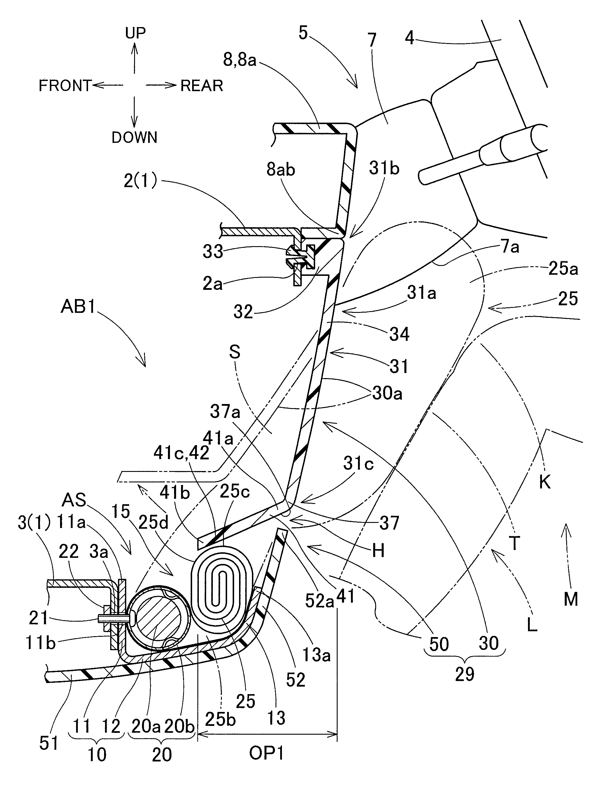
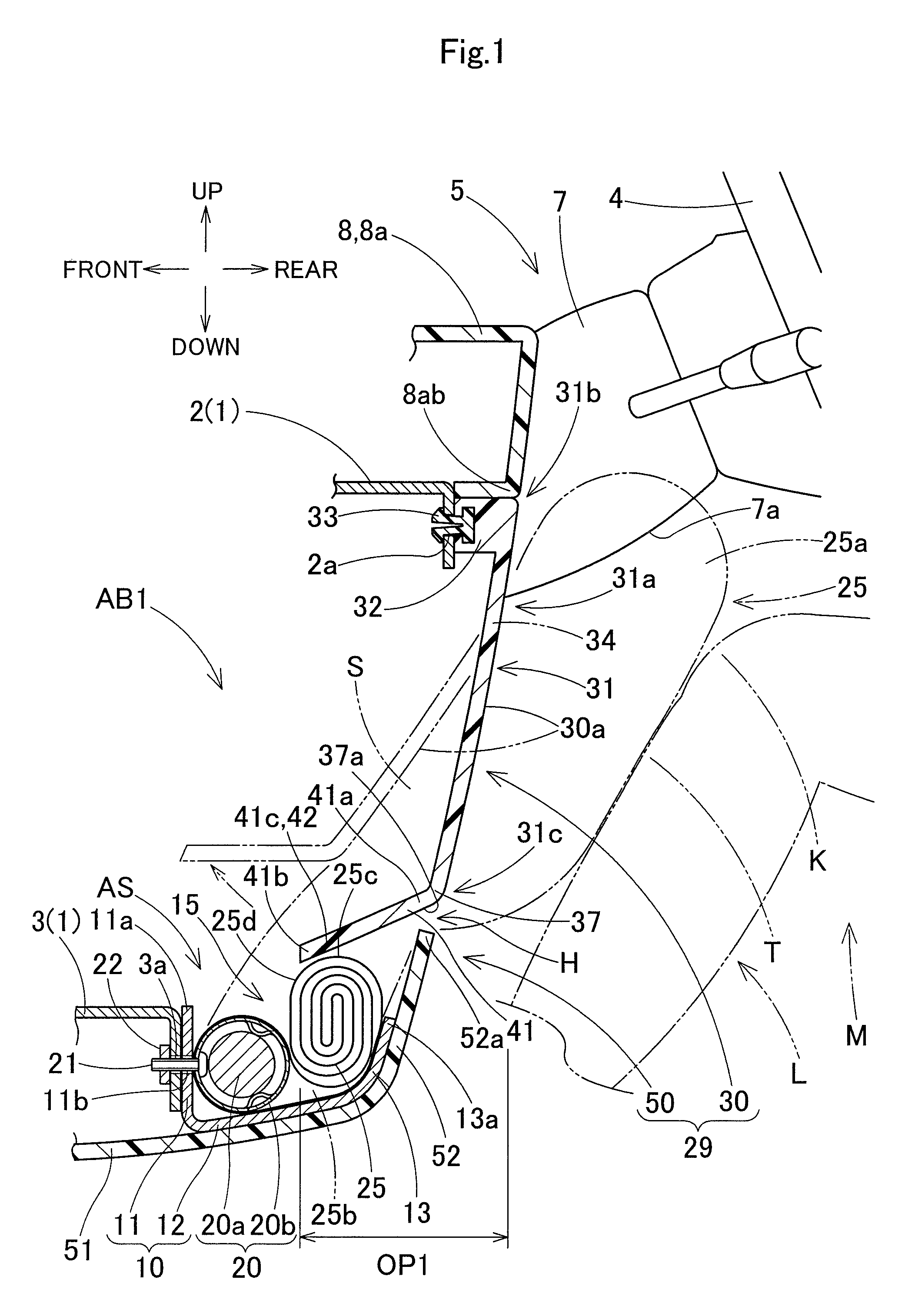
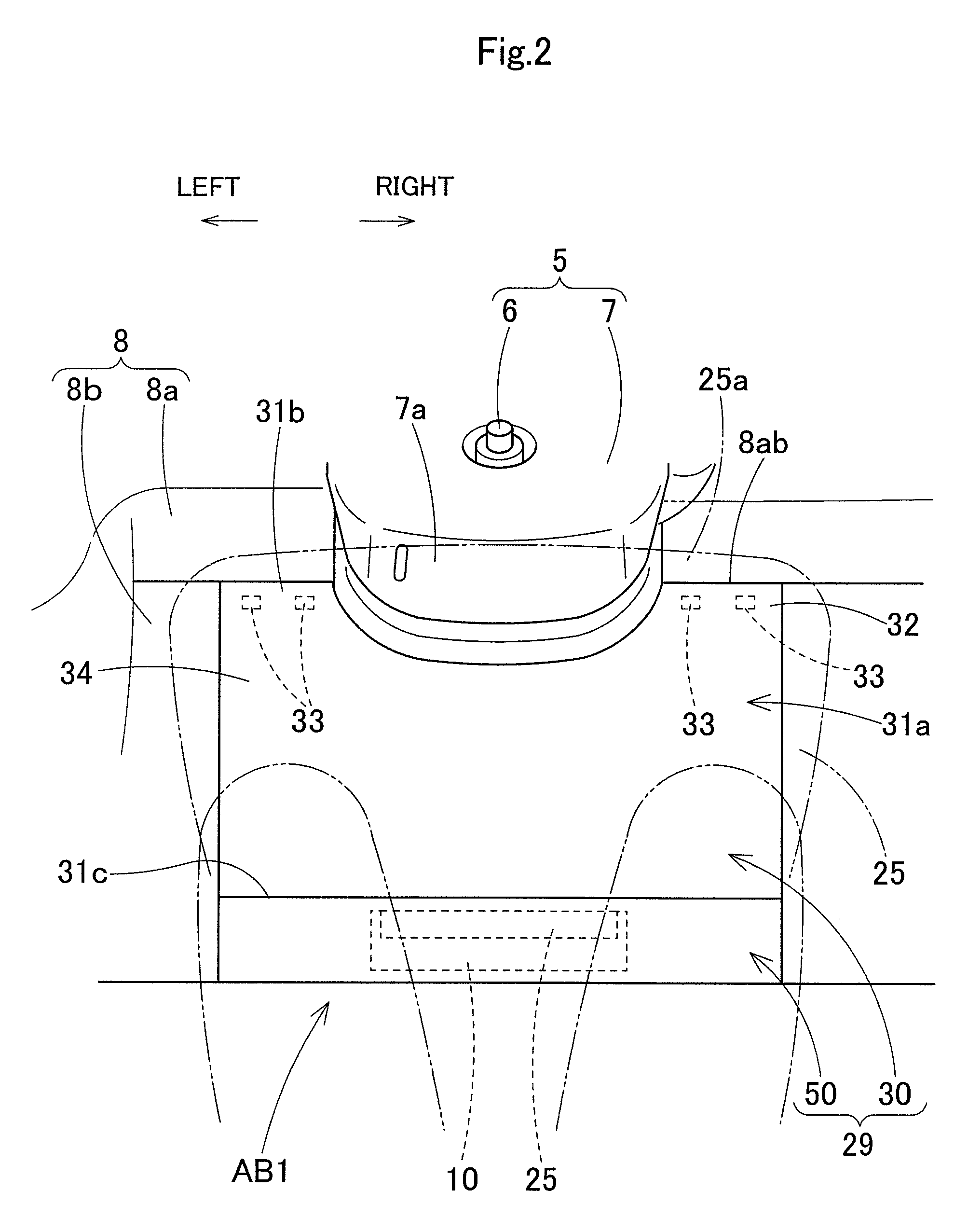
[0025]As illustrated in FIGS. 1 and 2, a knee protection airbag apparatus AB1 of an embodiment is provided below a steering column 5 positioned in front of a driver M in a vehicle, and can protect knees K of the driver M as an occupant sitting in the vehicle.

[0026]A vertical direction, a lateral direction, and a longitudinal direction in the specification correspond to a vertical direction, a lateral direction, and a longitudinal direction of the vehicle, respectively, when the knee protection airbag apparatus AB1 is mounted in the vehicle.

[0027]As illustrated in FIGS. 1 and 2, the steering column 5 includes a steering shaft 6 and a column cover 7. The steering sh...


PUM


Abstract

A knee protection airbag apparatus includes an airbag and a front panel. The front panel includes a lower panel portion and an upper panel portion. When the airbag inflates, the airbag causes the upper panel portion to move to the front, and deploys in a space on a rear surface-side of the moving upper panel portion. The upper panel portion includes a general portion of an upper portion and a ceiling wall portion of a lower portion. The lower panel portion is separate from the upper panel portion, and covers a rear side of the folded airbag. The upper panel portion includes a pressure receiving portion facing the folded airbag. The upper panel portion has the vicinity of the fixation portion of the general portion as a bending deformation portion that bends when the upper panel portion moves to the front along with the inflation of the airbag.

Description

[0001]The present application claims priority from Japanese Patent Application No. 2013-202914 of Ando et al., filed on Sep. 30, 2013, the disclosure of which is hereby incorporated into the present application by reference.BACKGROUND OF THE INVENTION[0002]1. Field of the Invention[0003]The present invention relates to a vehicle mounted knee protection airbag apparatus that can protect the knees of an occupant sitting in a vehicle.[0004]2. Description of Related Art[0005]As illustrated in FIGS. 1 to 4 and FIG. 7 disclosed in JP-A-8-80797, a knee protection airbag apparatus of the related art has a space for deployment and inflation of an airbag formed in front of the knees of an occupant during an operation of the airbag. The airbag apparatus includes the airbag and a front panel. The airbag is accommodated in a folded state in front of the lower limbs of the sitting occupant. The front panel is provided in front of the lower limbs of the occupant along a substantially vertical dire...

Claims


Application Information

Patent Timeline
Patent Type & Authority Patents(United States)
IPC IPC(8): B60R21/206B60R21/16B60R21/00
CPCB60R21/206B60R2021/0051B60R2021/161
Inventor ANDO, TAKESHIKOMATSU, TAKANORIOGATA, TETSUYAMURASE, HIROKI
Owner TOYODA GOSEI CO LTD
Why Eureka
Try Eureka