
Force-rebalance coriolis vibratory gyroscope

a vibrating gyroscope and force-rebalance technology, applied in the direction of speed measurement using gyroscopic effects, instruments, surveying and navigation, etc., can solve the problems of drift errors, poor performance, and performance improvemen

Active Publication Date: 2015-10-13
INNALABS
View PDF9 Cites 12 Cited by
  • Summary
  • Abstract
  • Description
  • Claims
  • Application Information

AI Technical Summary

Benefits of technology

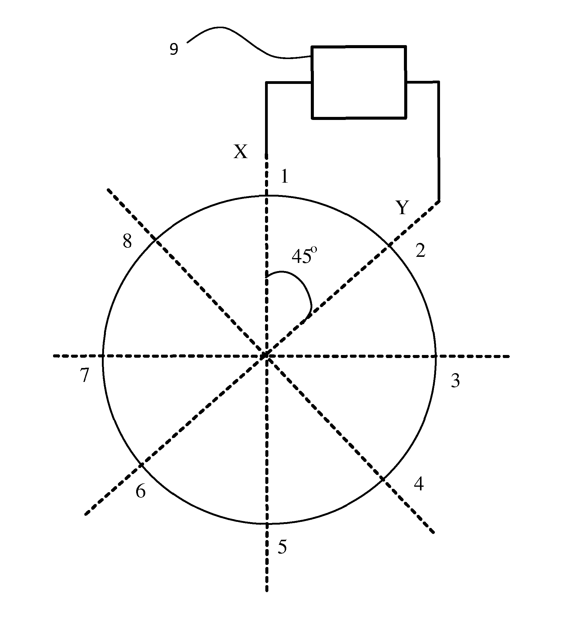
The present invention is related to a new design for a Coriolis Vibrating Gyroscope (CVG) that solves several problems of previous designs. The new design uses an axisymmetrical resonator and is driven and controlled through its second order vibration modes (elliptical shape) or first order vibration modes (for example, bending of beams). The excitation of the vibration mode along the Y-axis is performed, and the sensitive axis of the gyroscope is reversed by 180 degrees. This allows for the cancellation of errors caused by zero-bias and its changes over time and temperature. The use of a second additional coaxial gyroscope provides high accuracy in measuring angular velocity during the transition process. The electrodes system for X-axis is obtained by rotating the electrodes system for Y-axis by 45 degrees. The invention has advantages over previous designs and provides a more efficient and accurate way to measure angular velocity.

Problems solved by technology

Unfortunately, reduction in size does not mean improvement in performance.
The mismatch in frequencies is important because this leads to drift errors and poor performances.
However, all gyroscopes described in the above patents have some imperfections due to material inhomogeneities, due to machining imprecision, but also due to drive and sense elements misplacements.
All these errors are responsible of mismatch in frequencies, damping and mismatch in damping.
Thus, a significant zero-bias error appears which depends on temperature and time.
This process of calibration is time consuming and expensive.
Additionally, materials ages and their properties change over time.
As a result, conventional calibrations are not robust and effective.
However, this method compensates only one source of error and does not compensate for other sources, such as effect of mismatch in damping and frequencies.

Method used


Image

  • Force-rebalance coriolis vibratory gyroscope
  • Force-rebalance coriolis vibratory gyroscope
  • Force-rebalance coriolis vibratory gyroscope

Examples


Embodiment Construction

[0043]Reference will now be made in detail to the preferred embodiments of the present invention, examples of which are illustrated in the accompanying drawings.

[0044]An effective and more precise method and system for compensation of a zero-bias in a gyroscope is provided. An excitation of vibration mode along the X-axis is performed. The angular velocity is measured by measuring the amplitude of the Coriolis mode along the Y-axis. The sensitivity axis of the gyroscope is reversed by 180 degrees by reversing electrodes acting on X-axis and Y-axis.

[0045]The excitation signal is fed to the electrode mounted along the X-axis and is measured along the Y-axis. After a time period T, the excitation signal is fed to the electrode mounted along the Y-axis and is measured along the X-axis. Thus, the position of a standing wave is alternately changed. The sign of the measured angular velocity of the output signal of the gyroscope changes as well.

[0046]According to an exemplary embodiment in ...


PUM


Abstract

An effective and precise method and system for compensation and measurement of a zero-bias in an axisymmetrical CVG (Coriolis Vibrating Gyroscope) is provided. Principal mode is driven according to an X-axis. Angular velocity is measured through Coriolis mode excitation along Y-axis. The sensitive axis of the gyroscope is reversed by 180 degrees by switching input and sense signals. Vibration is then driven along Y-axis and angular velocity is sensed along X-axis. On each position, after an arbitrary period of time, the gyroscope output is stored. Half-difference in outputs between two opposite position gives angular velocity and zero-bias effect is canceled. Half-sum in outputs between two opposite position gives the zero-bias error.

Description

BACKGROUND OF THE INVENTION[0001]1. Field of the Invention[0002]The present invention is related to a Force-Rebalance Coriolis Vibrating Gyroscope (CVG), and more particularly, to an axisymmetrical gyroscope such as a ring, a cylindrical, a hemispherical, or tuning forks gyroscopes.[0003]2. Description of the Related Art[0004]A gyroscope is a device for measuring or maintaining orientation. Applications of gyroscopes include inertial navigation (INS), stabilization of ground vehicles, aircraft, ships, and line of sights, piloting etc. . . .[0005]Conventional vibrating gyroscopes are disclosed in the following U.S.[0006]Patents: U.S. Pat. No. 6,698,271, U.S. Pat. No. 7,120,548, U.S. Pat. No. 7,240,533, U.S. Pat. No. 7,216,525, U.S. Pat. No. 7,281,425, U.S. Pat. No. 5,597,955. Vibrating gyroscopes (i.e., gyroscopes based on vibrating structures) have many advantages over traditional spinning gyroscopes (i.e., based on a rapidly spinning mass), but also over gyroscopes based on fiber-o...

Claims


Application Information

Patent Timeline
IPC IPC(8): G01C19/00G01C19/5677G01C25/00
CPCG01C25/00G01C19/5677G01C19/5691
Inventor BEITIA, JOSEOKON, ISAAK M.SIMONENKO, DMITRI V.RENAULT, ALAIN
Owner INNALABS
Learn More