Adjusting device for headlights

a technology for adjusting devices and headlights, which is applied in fixed installation, electric lighting, lighting and heating apparatus, etc. it can solve the problems of large installation space, large number of components, and achieve low static friction and distorting light image.

Active Publication Date: 2015-10-13
HELLA KG HUECK & CO
View PDF13 Cites 0 Cited by
  • Summary
  • Abstract
  • Description
  • Claims
  • Application Information

AI Technical Summary

Benefits of technology

[0006]According to the invention, a linear element is braced on the adjusting point opposite a carrier and / or a luminous component of the headlight by way of a deformation element, which makes the co-movement transversely to the direction of adjustment possible due to its deformability or flexibility if a mechanical force is applied in the direction of the linear element. Because the longitudinal axis of the linear element does not cross an adjusting axis, a rotating motion of the luminous component relative to the stationary carrier occurs if an axial deformation force is applied onto the linear element, wherein the deformation element is co-moveable in the direction of an adjusting pathway running transversely to the axis of the linear element. Advantageously, the deformation element can be deformed without introducing any undesirable tensions. After adopting the adjusting position, the deformation element enables a sufficiently secure mount of the luminous component. Compared to traditional deformation elements made of rubber material, the deformation element according to the invention has the advantage that no material of the deformation element is flowing into the gap between the carrier and highway beam reflector during the adjustment. Said type of behavior would have the disadvantage that the linear element is unable to move along an adjusting pathway running transversely to the longitudinal axis of the latter, thus resulting in the undesirable introduction of bending moments into the luminous component and hence distorting the light image. Furthermore, the use of rubberized deformation elements would generate shearing stress in the rubber material which impairs the mobility of the rubberized deformation element in the transverse direction. Moreover, rubberized deformation elements do not guarantee a vibration-proof adjustment, meaning that the support of the luminous component would be “floating,” thus requiring a separate fixation of the luminous component. The special feature of the deformation element according to the invention is that the static friction is identical or negligibly greater than the kinetic friction. In terms of the frictional effect, the deformation element acts as if the areas of contact of the solids facing each other consisted of ice material if a force is applied perpendicular to the areas of contact of the deformation element onto an adjacent solid. Correspondingly, the deformation element according to the invention has a relatively low static friction.
[0007]According to a preferred embodiment of the invention, the deformation element is designed as a bushing arranged slipped onto the linear elements and positioned between the carrier and a support ring of the linear elements or between the carrier and the luminous component. By applying an adjusting force running in the direction of the linear element, which can be brought about for example by tightening a nut which has a threaded connection with the linear element, the deformation element can be compressed in the normal direction along a normal adjusting pathway component on the one hand and co-moved in transverse direction to the adjusting force (normal direction) relative to the carrier or the luminous component on the other hand. Said sliding properties of the deformation element enable the “migration” of the adjusting point around the adjusting axis. Once the adjusting process is complete, a secure mount of the luminous component is ensured, and the relative position of the luminous component to the carrier is not changing in connection with vibrations.

Problems solved by technology

The disadvantage of the disclosed adjusting device is that it requires a relatively large number of components and a large installation space.
The disadvantage of the disclosed adjusting device is that it requires a relatively large installation space.
Said type of behavior would have the disadvantage that the linear element is unable to move along an adjusting pathway running transversely to the longitudinal axis of the latter, thus resulting in the undesirable introduction of bending moments into the luminous component and hence distorting the light image.
Furthermore, the use of rubberized deformation elements would generate shearing stress in the rubber material which impairs the mobility of the rubberized deformation element in the transverse direction.
Moreover, rubberized deformation elements do not guarantee a vibration-proof adjustment, meaning that the support of the luminous component would be “floating,” thus requiring a separate fixation of the luminous component.

Method used


Image

  • Adjusting device for headlights
  • Adjusting device for headlights
  • Adjusting device for headlights

Examples


Embodiment Construction

[0018]In the following detailed description numerous specific details are set forth in order to provide a thorough understanding of the invention. However, it will be understood by those skilled in the art that the present invention may be practiced without these specific details. For example, the invention is not limited in scope to the particular type of industry application depicted in the figures. In other instances, well-known methods, procedures, and components have not been described in detail so as not to obscure the present invention.

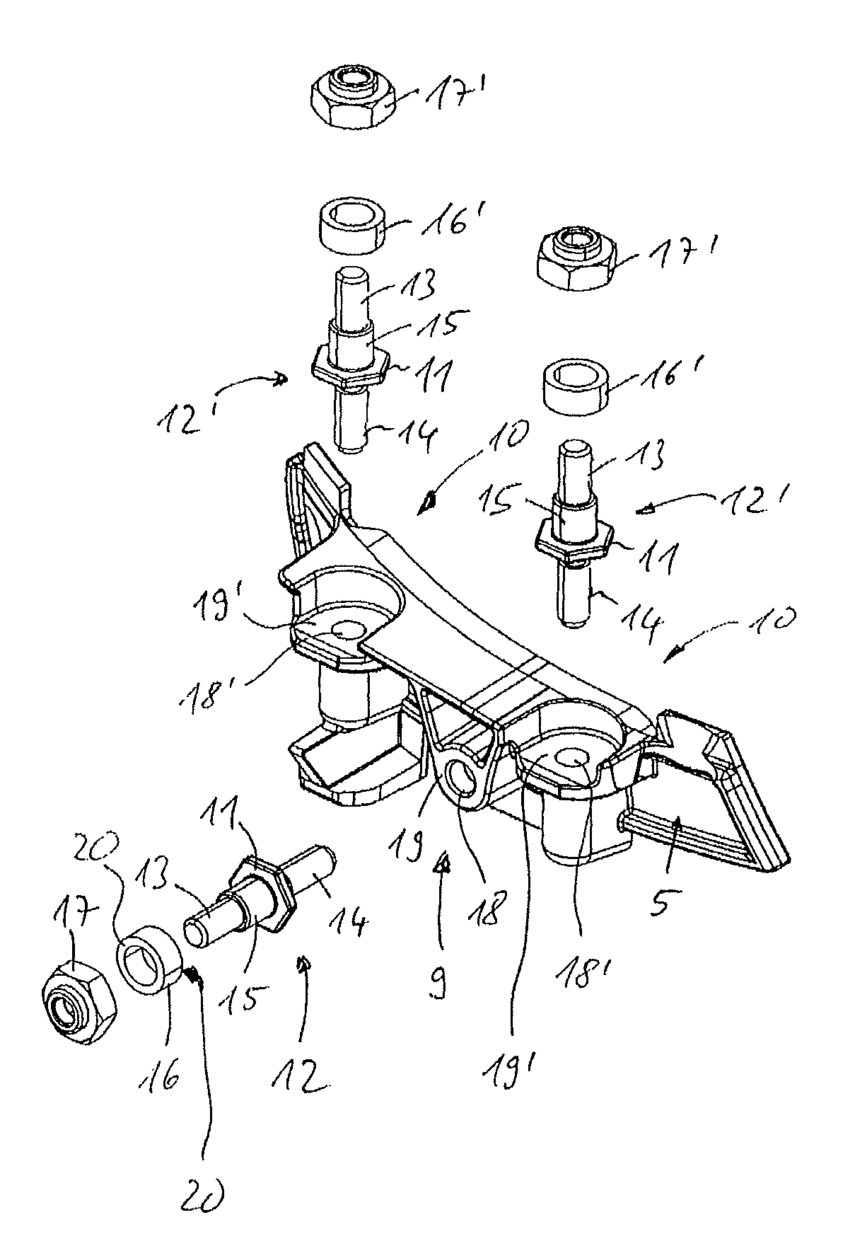
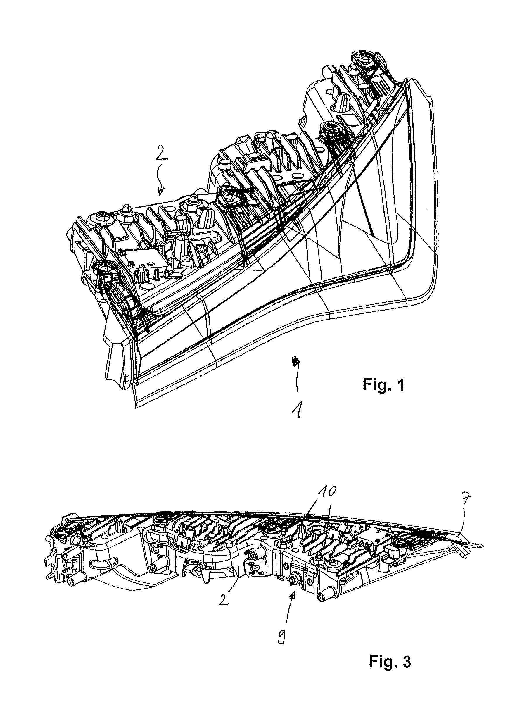
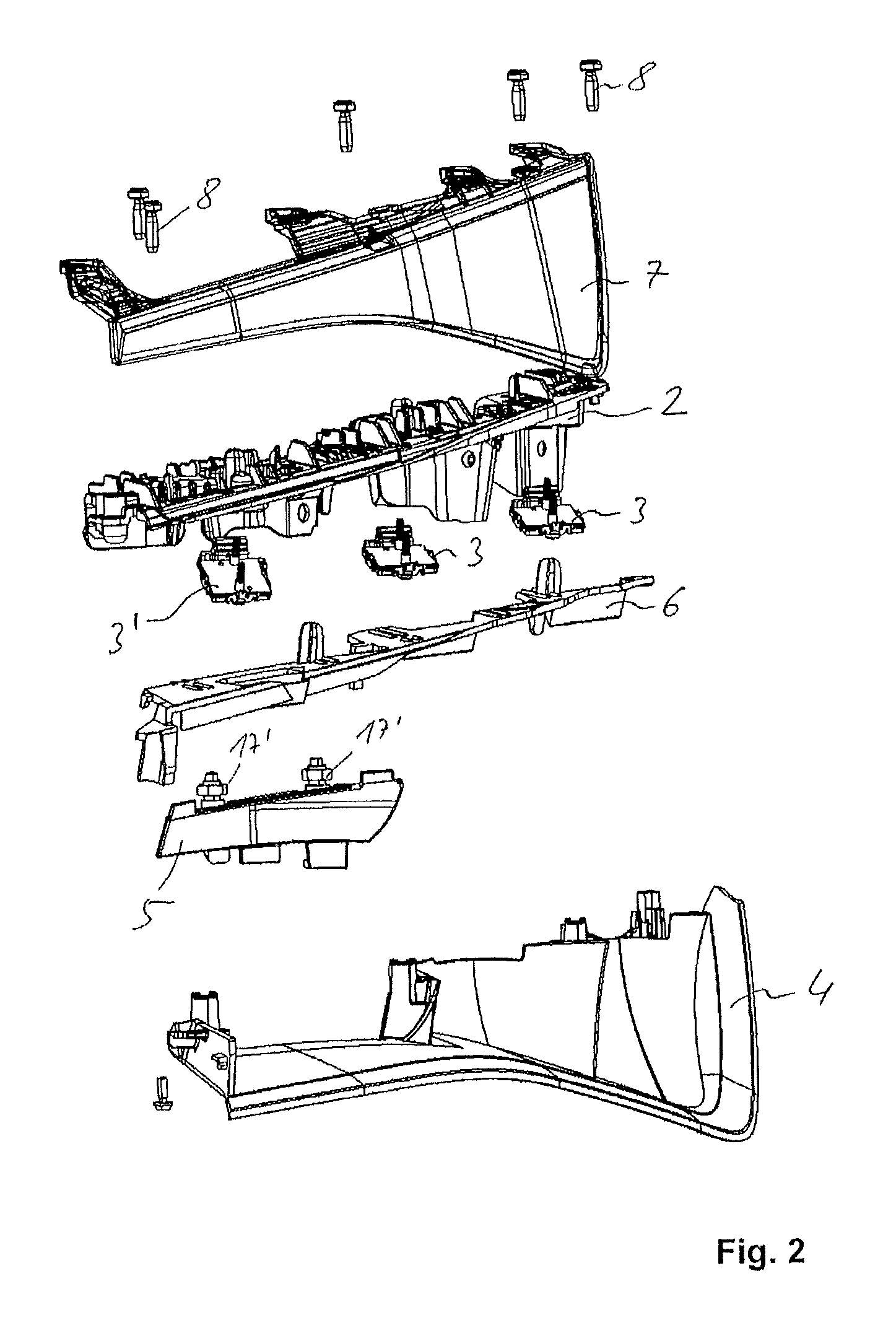
[0019]A headlight 1 according to the invention is used to generate a high beam distribution and a highway beam distribution in the frontal area of a motor vehicle.

[0020]The headlight 1 comprises a carrier 2 designed as a cooling element, from one side of which LED light sources 3, 3′ are mounted. The two LED light sources 3 cooperate with a high beam reflector 4 as luminous component to generate a high beam distribution. The single LED light so...


PUM


Abstract

An adjusting device for headlights has a luminous component supported on a carrier and a linear element for angling the luminous component around a horizontal and / or vertical adjusting axis, which is acting upon said component and arranged on an adjusting point, wherein in the region of the linear element, the luminous component is supported on areas of contact opposite the carrier and / or the luminous component by way of said type of deformation element such that if an adjusting force is applied onto the areas of contact in the normal direction, the deformation element is moveable together with the luminous component along an adjusting pathway running perpendicular to the normal direction.

Description

TECHNICAL FIELD OF THE INVENTION[0001]The invention relates to an adjusting device for headlights having a luminous component supported on a carrier and having a linear element for angling the luminous component around a horizontal and / or vertical adjusting axis which is acting onto said luminous component and arranged on an adjusting point.BACKGROUND OF THE INVENTION[0002]An adjusting device for headlights is disclosed in DE 102 38 792 A1, in which a luminous component, namely a reflector is adjustable around a horizontal adjusting axis by means of linear elements. The adjusting axis is formed with two separate movable support points of the luminous component to the carrier. To angle the luminous component around the horizontal adjusting axis, the linear elements, which have a threaded connection with the luminous component, are rotated around their axis such that the rotating motion of the adjusting element is converted into a longitudinal motion in the direction of adjustment. Th...

Claims


Application Information

Patent Timeline
Patent Type & Authority Patents(United States)
IPC IPC(8): F21S8/10
CPCF21S48/1159F21S48/1757F21S48/328F21S48/1104F21S41/19F21S41/147F21S41/675F21S45/47F21S41/151F21S45/48
Inventor PA.BETA.GANG, FRANKPOLENZ, KAITSCHERNECK, DENNIS
Owner HELLA KG HUECK & CO
Why Eureka
Try Eureka