High-frequency module

a technology of high-frequency modules and modules, applied in the field of high-frequency modules, can solve the problems of difficult to sufficiently enhance and achieve the effect of preventing the deterioration of the sensitivity characteristic of a communication system

Active Publication Date: 2015-10-06
MURATA MFG CO LTD
View PDF12 Cites 0 Cited by
  • Summary
  • Abstract
  • Description
  • Claims
  • Application Information

AI Technical Summary

Benefits of technology

[0007]In view of such a point, preferred embodiments of the present invention provide a high-frequency module in which a plurality of demultiplexer chips are installed, the high-frequency module preventing the deterioration of the sensitivity characteristic of a communication system.
[0013]According to various preferred embodiments of the present invention, a high-frequency module includes a plurality of demultiplexer chips and prevents deterioration of the sensitivity characteristic of a communication system.

Problems solved by technology

However, when the high-frequency module is used in which the plural demultiplexer chips are installed, in some cases it is difficult to sufficiently enhance the sensitivity characteristic of a communication system.

Method used


Image

  • High-frequency module
  • High-frequency module
  • High-frequency module

Examples


Embodiment Construction

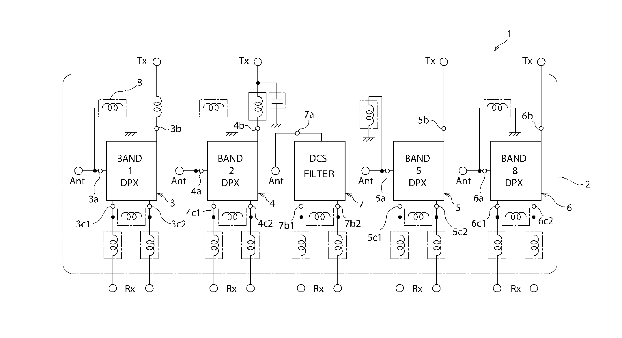
[0028]Hereinafter, preferred embodiments in which the present invention is implemented will be described based on, as an example, a duplexer module 1 serving as a high-frequency module. In this regard, however, the duplexer module 1 is just an exemplification and is not limiting of the present invention. A high-frequency module according to the present invention is not limited to the duplexer module 1. It may be only necessary for the high-frequency module according to a preferred embodiment of the present invention to include a plurality of demultiplexer chips, and the high-frequency module according to a preferred embodiment of the present invention may also include, for example, a triplexer chip.

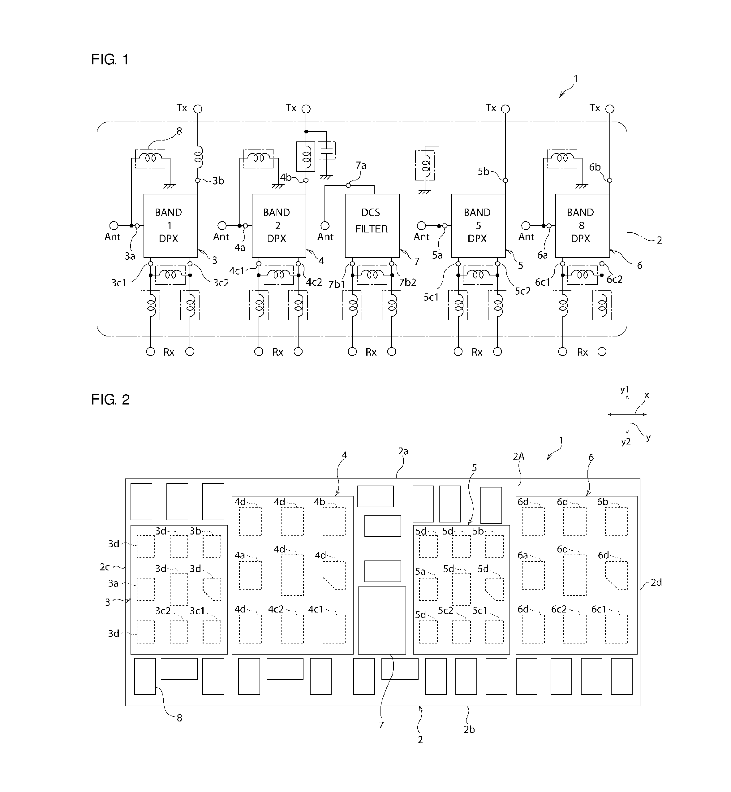
[0029]The duplexer module 1 of the present preferred embodiment is, for example, a duplexer module installed in an RF circuit in a communication device such as a cellular phone. FIG. 1 is the schematic circuit diagram of the duplexer module 1 of the present preferred embodiment. FIG. 2 is...


PUM


Abstract

In a high-frequency module, an arrangement order of antenna terminals, transmission-side signal terminals, and reception-side signal terminals in a second direction corresponds to an arrangement order of antenna terminal electrodes, transmission-side terminal electrodes, and reception-side terminal electrodes in the second direction.

Description

BACKGROUND OF THE INVENTION[0001]1. Field of the Invention[0002]The present invention relates to a high-frequency module. In particular, the present invention relates to a high-frequency module in which a plurality of demultiplexer chips are mounted on a mounting substrate.[0003]2. Description of the Related Art[0004]High-frequency modules, in each of which a filter chip and a chip component are installed on a mounting substrate, have been used for cellular phones and the like. For example, in WO 2008 / 023510 A1, a high-frequency module is described in which a plurality of elastic wave filter chips and a plurality of chip inductors are mounted on a mounting substrate.[0005]In recent years, communication systems have been shifting from a 2G system mainly including GSM (registered trademark) to a 3G system such as UMTS. So as to deal with this 3G system, it may also be considered that a plurality of demultiplexers chip such as duplexer chips are installed in a high-frequency module, ea...

Claims


Application Information

Patent Timeline
Patent Type & Authority Patents(United States)
IPC IPC(8): H01Q21/00H01Q21/28H03H9/05H03H9/64H03H9/70H03H9/72H04B1/52H03H9/00
CPCH01Q21/28H03H9/0571H03H9/0576H03H9/6483H03H9/706H03H9/725H04B1/52H03H9/0028
Inventor NAGAI, TATSURO
Owner MURATA MFG CO LTD
Why Eureka
Try Eureka