
Turbine abradable layer with progressive wear zone multi level ridge arrays

a turbine engine and progressive wear technology, applied in the direction of machines/engines, stators, mechanical equipment, etc., can solve the problems of local variations in the blade tip gap, reducing the operational reducing the efficiency of the turbine engine, so as to improve engine efficiency performance and reduce the blade tip gap. , the effect of controlling the blade tip gap

Active Publication Date: 2015-10-06
SIEMENS ENERGY GLOBAL GMBH & CO KG
View PDF219 Cites 21 Cited by
  • Summary
  • Abstract
  • Description
  • Claims
  • Application Information

AI Technical Summary

Benefits of technology

This solution effectively reduces blade tip leakage and wear, enhances engine efficiency, and allows for a single design to operate in both standard and fast start modes, maintaining aerodynamic control and thermal integrity.

Problems solved by technology

Similarly, small mechanical alignment variances during engine assembly can cause local variations in the blade tip gap.
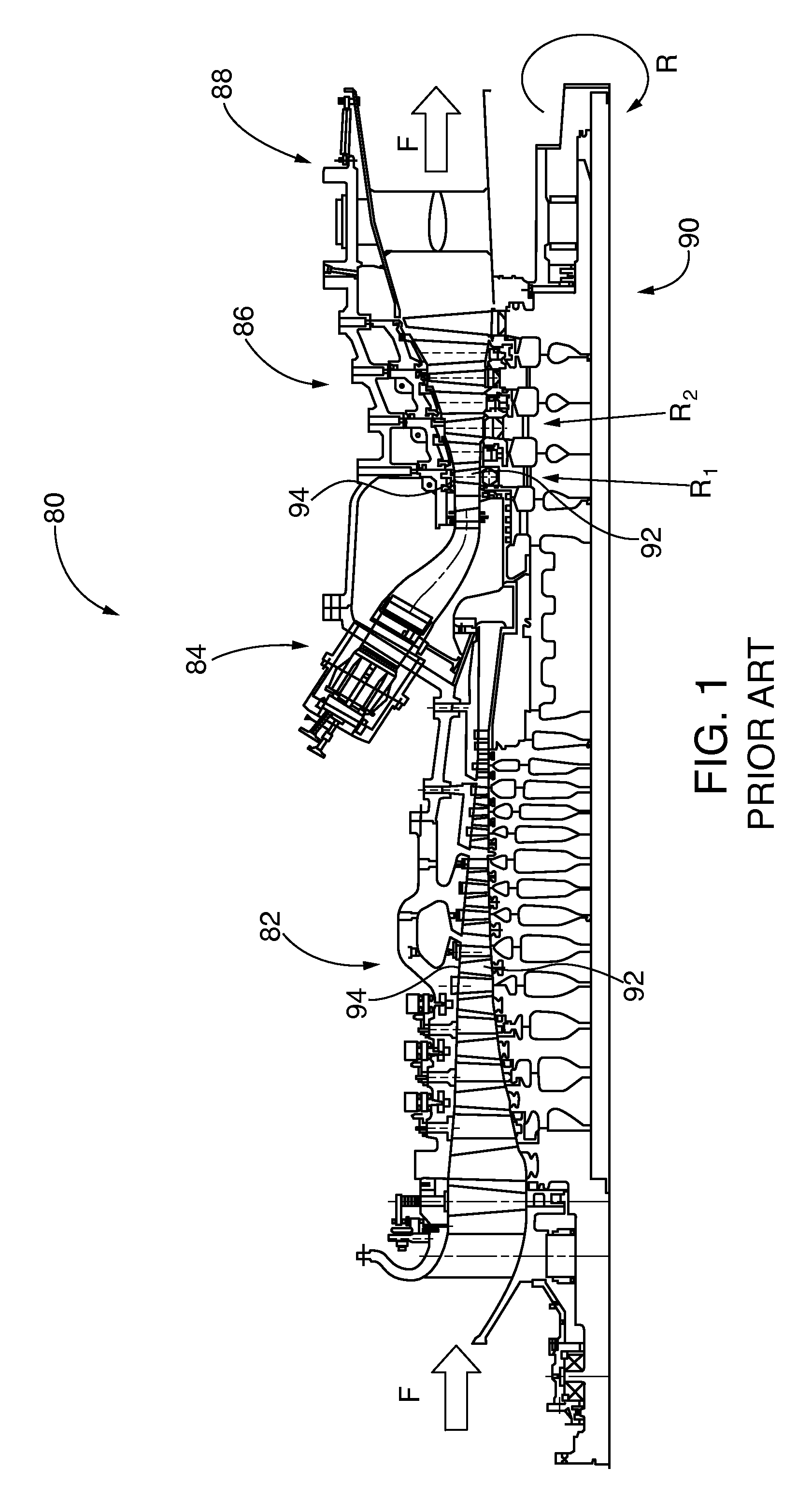
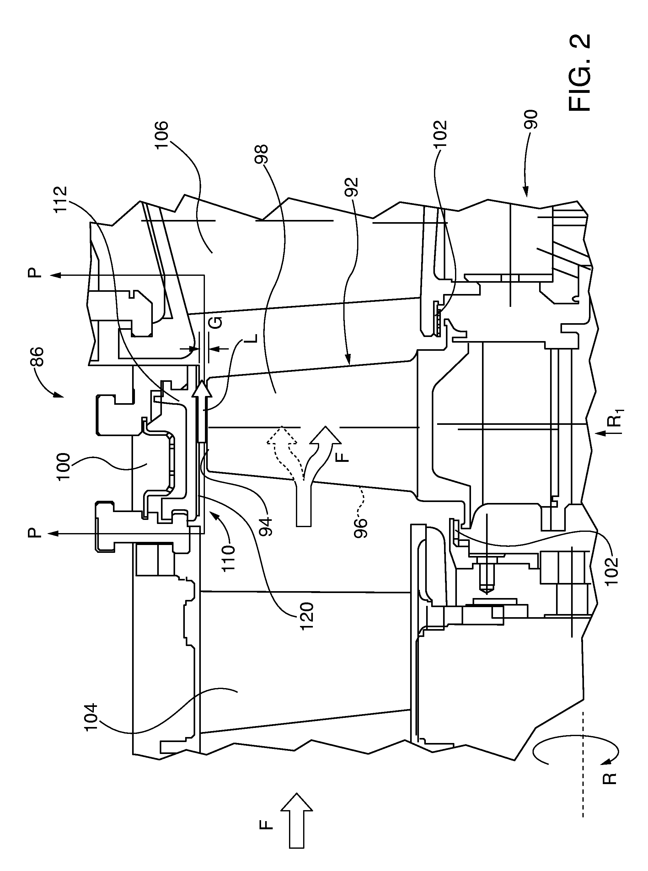
The excessive blade gap Gw distortion increases blade tip leakage L, diverting hot combustion gas away from the turbine blade 92 airfoil, reducing the turbine engine's efficiency.
Past abradable component designs have required stark compromises between blade tips wear resulting from contact between the blade tip and the abradable surface and blade tip leakage that reduces turbine engine operational efficiency.
Aggressive ramp-up rates exacerbated potential higher incursion of blade tips into ring segment abradable coating, resulting from quicker thermal and mechanical growth and higher distortion and greater mismatch in growth rates between rotating and stationary components.
Whether in standard or fast start configuration, decreasing blade tip gap for engine efficiency optimization ultimately risked premature blade tip wear, opening the blade tip gap and ultimately decreasing longer term engine performance efficiency during the engine operational cycle.
However groove dimensions were inherently limited by the packing spacing and diameter of the spheres in order to prevent sphere breakage.

Method used


Image

  • Turbine abradable layer with progressive wear zone multi level ridge arrays
  • Turbine abradable layer with progressive wear zone multi level ridge arrays
  • Turbine abradable layer with progressive wear zone multi level ridge arrays

Examples


embodiment 270

[0116]FIGS. 23-25 show embodiments of abradable component ridge and groove planform arrays that comprise zig-zag patterns. The zig-zag patterns are formed by adding one or more layers of material on an abradable surface substrate to form ridges or by forming grooves within the substrate, such as by known laser or water jet cutting methods. In FIG. 23 the abradable component 250 substrate surface 257 has a continuous groove 258 formed therein, starting at 258′ and terminating at 258″ defines a pattern of alternating finger-like interleaving ridges 252. Other groove and ridge zig-zag patterns may be formed in an abradable component. As shown in the embodiment of FIG. 24 the abradable component 260 has a continuous pattern diagonally oriented groove 268 initiated at 268′ and terminating at 268″ formed in the substrate surface 267, leaving angular oriented ridges 262. In FIG. 25 the abradable component embodiment 270 has a vee or hockey stick-like dual zone multi groove pattern formed b...

embodiment 320

[0125]FIG. 44 shows another stepped profile abradable component 330 with the ridges 332A / B having vertically oriented parallel side walls 335A / B and 336A / B. The lower ridge terminates in ridge plateau 334B, upon which the upper ridge 332A is oriented and terminates in ridge tip 334A. In some applications it may be desirable to employ the vertically oriented sidewalls and flat tips / plateaus that define sharp-cornered profiles, for airflow control in the blade tip gap. The upper wear zone I is between the ridge tip 334A and the ridge plateau 334B and the lower wear zone is between the plateau and the abradable surface 337. As with the abradable embodiment 320 of FIG. 43, while the ridges and grooves shown in FIG. 44 are symmetrically spaced, other spacing profiles may be chosen, including different ridge cross sectional profiles that create the stepped wear zones I and II.

[0126]In another permutation or species of stepped ridge construction abradable components, separate upper and low...

embodiment 350

[0127]As shown in FIG. 46, in certain turbine applications it may be desirable to control blade tip leakage by employing an abradable component 350 embodiment having asymmetric profile abradable ridges 352 with vertically oriented, sharp-edged upstream sidewalls 356 and sloping opposite downstream sidewalls 355 extending from the substrate surface 357 and terminating in ridge tips 354. Blade leakage L is initially opposed by the vertical sidewall 356. Some leakage airflow L nonetheless is compressed between the ridge tip 354 and the opposing blade tip 94 while flowing from the high pressure blade side 96 to the lower pressure suction blade side 98 of the blade. That leakage flow follows the downward sloping ridge wall 355, where it is redirected opposite blade rotation direction R by the vertical sidewall 356 of the next downstream ridge. The now counter flowing leakage air L opposes further incoming leakage airflow L in the direction of blade rotation R. Dimensional references show...


PUM

PropertyMeasurementUnit
trailing edge angleaaaaaaaaaa
heightaaaaaaaaaa
heightaaaaaaaaaa

Abstract

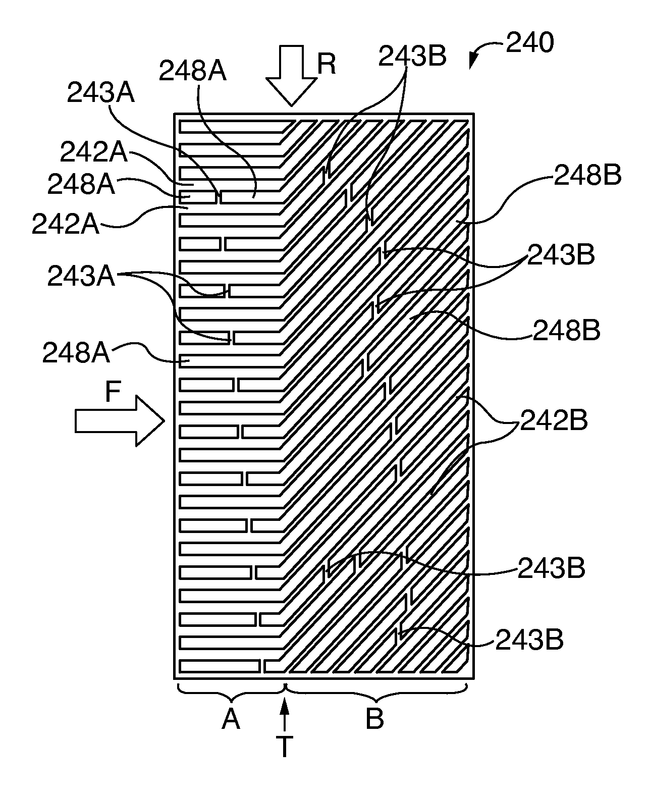
Turbine and compressor casing abradable component embodiments for turbine engines, with composite grooves and vertically projecting alternating rows of first and second height ridges in planform patterns, to reduce, redirect and / or block blade tip airflow leakage downstream into the grooves rather than from turbine blade airfoil high to low pressure sides. The first ridges have a first ridge height greater than that of the second ridges. These ridge or rib embodiments have first lower and second upper wear zones. The lower zone, at and below the second ridge height, optimizes engine airflow characteristics, while the upper zone, between tips of the second and first ridges, is optimized to minimize blade tip gap and wear by being more easily abradable than the lower zone.

Description

CROSS-REFERENCE TO RELATED APPLICATIONS[0001]The following United States patent applications, including this application were concurrently filed:[0002]“TURBINE ABRADABLE LAYER WITH PROGRESSIVE WEAR ZONE TERRACED RIDGES”, filed herewith and assigned Ser. No. 14 / 188,992;[0003]“TURBINE ABRADABLE LAYER WITH PROGRESSIVE WEAR ZONE MULTI DEPTH GROOVES”, filed herewith and assigned Ser. No. 14 / 188,813;[0004]“TURBINE ABRADABLE LAYER WITH PROGRESSIVE WEAR ZONE HAVING A FRANGIBLE OR PIXELATED NIB SURFACE”, filed herewith and assigned Ser. No. 14 / 188,941;[0005]“TURBINE ABRADABLE LAYER WITH ASYMMETRIC RIDGES OR GROOVES”, filed herewith and assigned Ser. No. 14 / 189,035;[0006]“TURBINE ABRADABLE LAYER WITH ZIG-ZAG GROOVE PATTERN”, filed herewith and assigned Ser. No. 14 / 189,081; and[0007]“TURBINE ABRADABLE LAYER WITH NESTED LOOP GROOVE PATTERN”, filed herewith and assigned Ser. No. 14 / 189,011.[0008]This application incorporates by reference all of the other above-cited related applications as if th...

Claims


Application Information

Patent Timeline
Patent Type & Authority Patents(United States)
IPC IPC(8): F01D11/12
CPCF01D11/122F05D2230/31F05D2250/28F05D2300/611C23C4/134C23C16/22F01D5/288F01D9/023F01D9/041F05D2220/32F05D2230/311F05D2230/312F05D2230/90F05D2240/35F05D2250/13F05D2300/10F05D2300/5023C23C4/02F01D5/187F01D5/286F01D25/12F05D2230/21F05D2260/202
Inventor THAM, KOK-MUNLAURELLO, VINCENT P.LEE, CHING-PANGAZAD, GM SALAMMARTIN, JR., NICHOLAS F.SANSOM, DAVID G.HITCHMAN, NEIL
Owner SIEMENS ENERGY GLOBAL GMBH & CO KG
Learn More