
Systems and methods for acoustic resonance mitigation

a technology of acoustic resonance and mitigation methods, applied in the field of acoustic mitigation, can solve problems such as unsatisfactory high noise levels, and achieve the effects of reducing the acoustic noise signature of the exhaust por

Active Publication Date: 2015-09-29
THE BOEING CO
View PDF21 Cites 1 Cited by
  • Summary
  • Abstract
  • Description
  • Claims
  • Application Information

AI Technical Summary

Benefits of technology

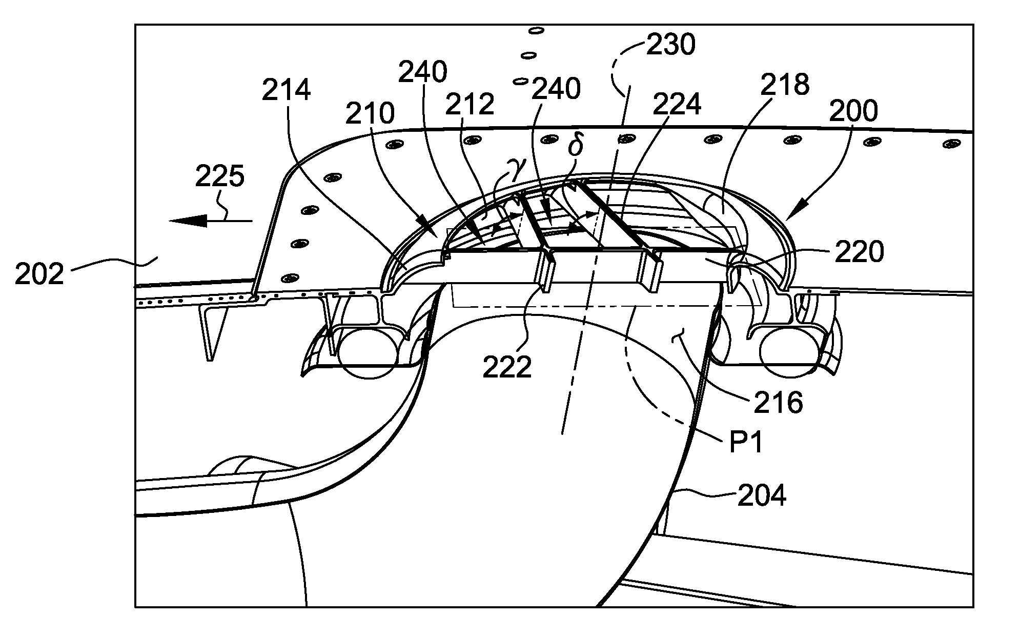
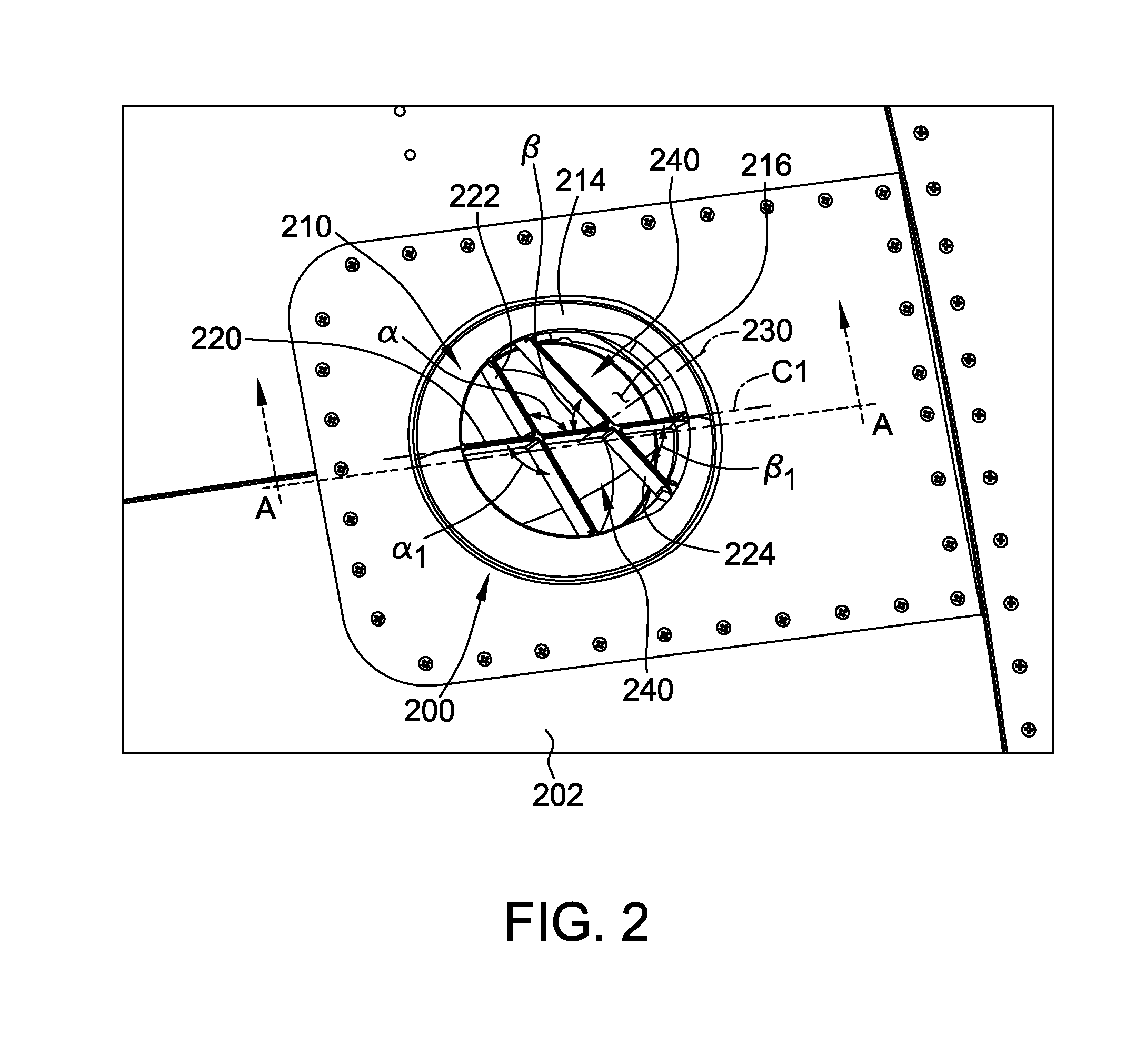
[0003]In one aspect, an exhaust acoustic noise reduction apparatus is provided. The exhaust acoustic noise reduction apparatus includes an exhaust port comprising an exhaust aperture, a first vane extending at least partially across the exhaust aperture, and a second vane extending at least partially across the exhaust aperture and intersecting the first vane, such that the first and second vanes are oriented to interfere with formation of an acoustic feedback loop and reduce an acoustic noise signature of the exhaust port.
[0004]In another aspect, a vehicle is provided. The vehicle includes an engine having a housing and an exhaust port coupled to the housing. The exhaust port includes an exhaust aperture, a first vane extending at least partially across the exhaust aperture, and a second vane extending at least partially across the exhaust aperture and intersecting the first vane, such that the first and second vanes are oriented to interfere with formation of an acoustic feedback loop and reduce an acoustic noise signature of the exhaust port.
[0005]In yet another aspect, a method of operating a vehicle including an exhaust port coupled to the vehicle is provided. The method includes coupling the exhaust port to the vehicle, wherein the exhaust port includes a first vane extending at least partially across the exhaust aperture and a second vane extending at least partially across the exhaust aperture and intersecting the first vane, such that the first and second vanes are oriented to interfere with the formation of the acoustic feedback loop and reduce the acoustic noise signature of the exhaust port; and exhausting a portion of at least one of air and fluid from the exhaust port.

Problems solved by technology

This feedback loop can excite the acoustic resonances of the air cavity and result in undesirably high noise levels.

Method used


Image

  • Systems and methods for acoustic resonance mitigation
  • Systems and methods for acoustic resonance mitigation
  • Systems and methods for acoustic resonance mitigation

Examples


Embodiment Construction

[0011]The systems and methods described herein facilitate reducing an acoustic noise signature of an exhaust port of a vehicle. As used herein, the term “vehicle” or “aircraft” may include, but is not limited to only including, airplanes, unmanned aerial vehicles (UAVs), gliders, helicopters, and / or any other object that travels through airspace. As used herein the terms “noise”, “acoustic resonance”, “acoustic noise”, or “acoustic noise signature” are the sounds produced by vibrations resulting from a feedback loop in which portions of an air flow are separated and impacts a downstream surface which produces acoustic pressure waves that travel upstream and interact with the flow separation mechanism.

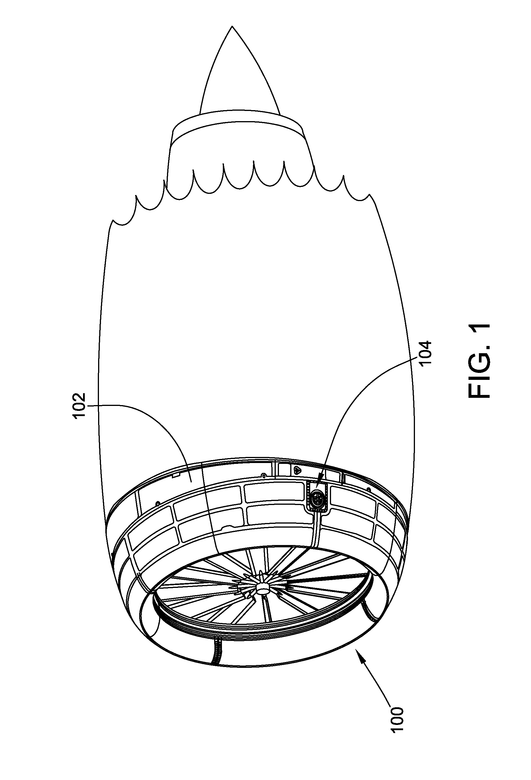
[0012]FIG. 1 is a perspective view of an exemplary engine 100 for use with an aircraft. Engine 100 includes a housing or nacelle 102 that substantially covers and directs airflow through and around engine 100. Housing 102 includes an exhaust port 104 configured to exhaust air and / or flu...


PUM


Abstract

Systems and methods for acoustic feedback or resonance mitigation are provided. The systems and methods include an exhaust acoustic noise reduction apparatus having an exhaust port comprising an exhaust aperture, a first vane extending at least partially across the exhaust aperture, and a second vane extending at least partially across the exhaust aperture and intersecting the first vane, such that the first and second vanes are oriented to interfere with formation of an acoustic feedback loop and reduce an acoustic noise signature of the exhaust port.

Description

BACKGROUND[0001]The field of the disclosure relates generally to acoustic mitigation, and more specifically, to methods and systems for mitigating acoustic resonance associated with exhaust ports.[0002]Generally, as air travels over an aperture, noise may be generated that corresponds to an acoustic resonance associated with the geometry of the aperture, an air cavity associated with the aperture, and / or air flow characteristics. In some known apertures, air flow moving over an aperture is separated from the leading edge of the aperture and takes the form of a shear layer and vortices. The separated flow impacts the trailing edge of the aperture which then generates an acoustic wave that travels upstream and interacts with the flow separation mechanism which ultimately forms an acoustic feedback loop. This feedback loop can excite the acoustic resonances of the air cavity and result in undesirably high noise levels. Some known vehicles (e.g. aircraft) may include apertures or ports ...

Claims


Application Information

Patent Timeline
Patent Type & Authority Patents(United States)
IPC IPC(8): F02C7/045F01N1/02B64D15/04B64D33/02
CPCF01N1/02B64D15/04B64D2033/0206B64D2033/0233
Inventor LAN, JUSTIN HONSHUNEVOGEL, STUART WILLIAMCOHEN, ROBERT L.
Owner THE BOEING CO
Learn More