
Ophthalmic surgical system and a control apparatus therefor

a control apparatus and ophthalmic surgery technology, applied in the field of ophthalmic surgery system and control apparatus therefor, can solve the problems of reducing the probability of injuring healthy tissue in the surroundings of the needle, reducing the probability of injuring the patient's eye, and reducing the quantity of supplied energy, so as to reduce the risk of eye damage to the patien

Active Publication Date: 2015-09-29
CARL ZEISS MEDITEC AG
View PDF7 Cites 13 Cited by
  • Summary
  • Abstract
  • Description
  • Claims
  • Application Information

AI Technical Summary

Benefits of technology

The invention provides a control apparatus for an ophthalmic surgical system that allows for phacoemulsification of the whole eye lens in a short period of time, with low risk of damage to the patient's eye. The control apparatus uses a hardness value of the eye lens particles to determine the optimal amount of ultrasound energy needed for breaking up the particles. This ensures that too much energy is not supplied, which could damage the surrounding healthy tissue. The control apparatus also ensures that only the minimum required energy input is supplied for breaking up the particles, reducing the risk of injury. The control apparatus is efficient, faster, and more reliable than manual control using a foot pedal. The invention also includes an occlusion determination device that measures the current used by the aspiration pump or the fluid flow in the aspiration line to detect an occlusion. The evaluation unit integrates the current quantities over a predetermined period of time to determine the hardness of the particle to be broken up in a more precise and reliable fashion.

Problems solved by technology

This reduces the probability of injuring healthy tissue in the surroundings of the needle, such as the cornea, by overheating.
This once again reduces the quantity of supplied energy and reduces the probability of injuring the patient's eye.
Nevertheless, only little time is expended in breaking up the lens particles.

Method used


Image

  • Ophthalmic surgical system and a control apparatus therefor
  • Ophthalmic surgical system and a control apparatus therefor
  • Ophthalmic surgical system and a control apparatus therefor

Examples


Embodiment Construction

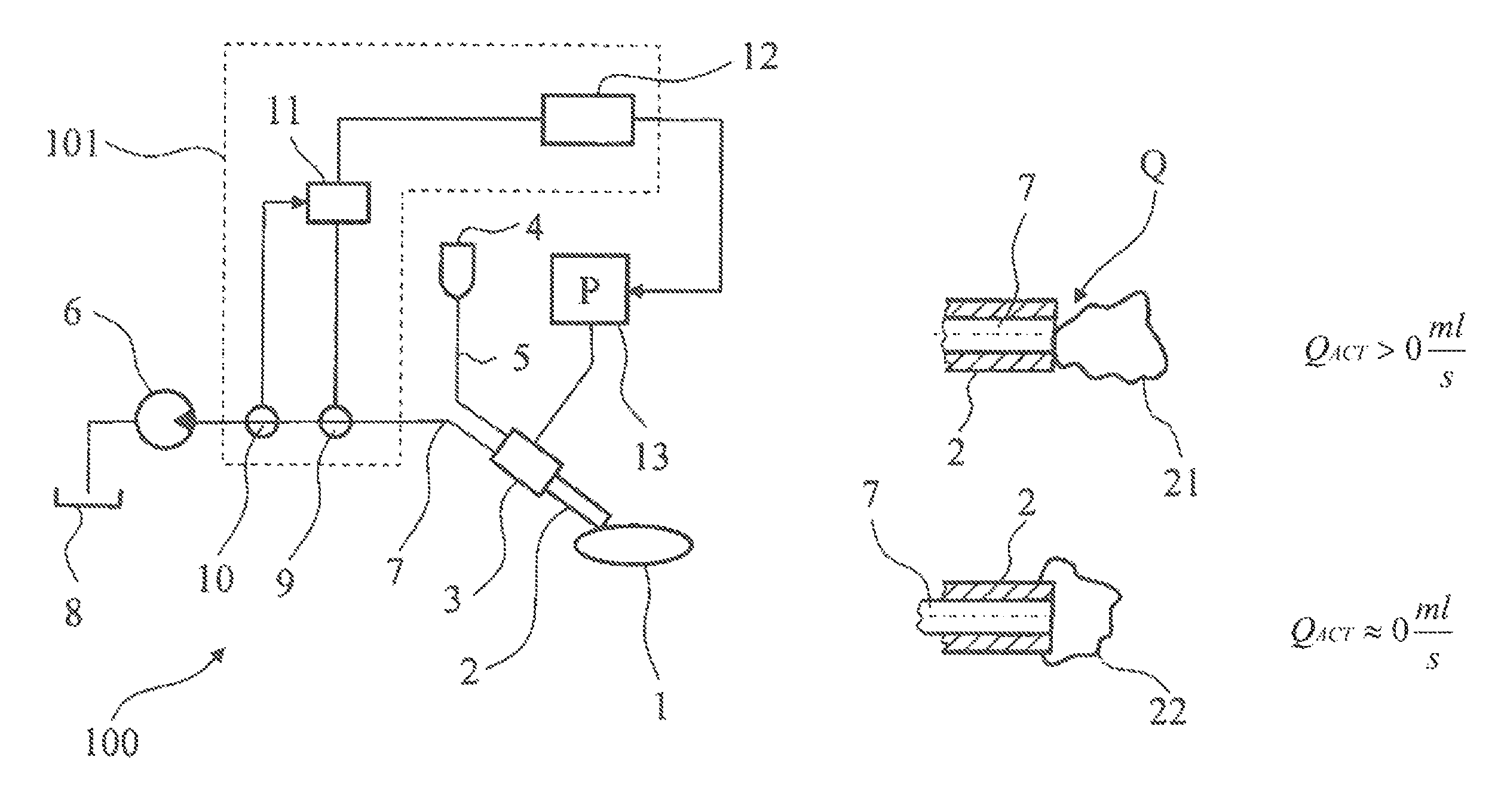
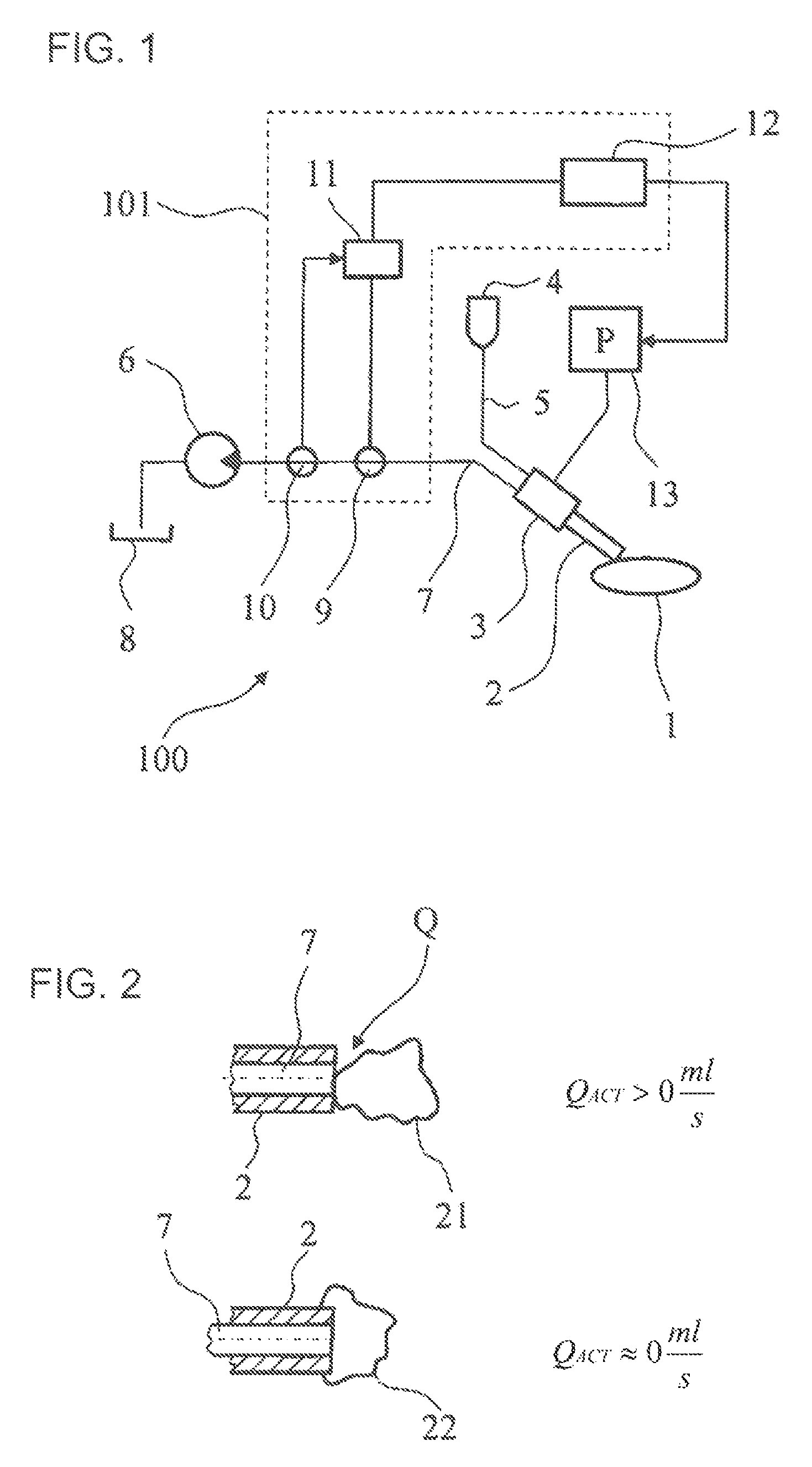
[0021]FIG. 1 shows a schematic illustration of an embodiment of an ophthalmic surgical system 100 with a control apparatus 101. An eye lens 1 to be treated is worked upon by a needle 2 of a handpiece 3 during phacoemulsification. Irrigation fluid flows, from an irrigation fluid container 4, through an irrigation line 5 to the handpiece 3 and there to a needle 2, the tip of which touches the eye lens 1. The supplied irrigation fluid and the broken-up lens particles are suctioned away via an aspiration line 7, which leads to an aspiration pump 5 through the needle 2 and the handpiece 3. The fluid and the particles are then caught in an aspiration container 8. Coupled to the aspiration line is a through-flow determination device 9, via which it is possible to determine an actual value of a fluid flow. Furthermore, an occlusion determination device 10 is provided along with the aspiration line 7, wherein the former can be used to determine whether there is an occlusion by a particle of ...


PUM


Abstract

A control device for an ophthalmic surgical system includes a flow determination device for determining an actual value of fluid flow in an aspiration line. The aspiration line is coupled to a handpiece for phacoemulsification of an eye lens and an occlusion determination device determines whether there is an occlusion because of a particle of the eye lens at a suction opening of the aspiration line. An evaluation unit establishes a hardness of the particle in dependence on the determined actual value of the fluid flow in the aspiration line should the occlusion determination device have determined that an occlusion is present, and, dependent on the hardness, determines a first value of ultrasound energy, which can be supplied to the handpiece by an energy source. A control unit actuates the energy source, during the occlusion, so that it outputs the determined first value of the ultrasound energy.

Description

CROSS REFERENCE TO RELATED APPLICATIONS[0001]This application is a continuation application of international patent application PCT / DE2011 / 001775, filed Sep. 24, 2011, designating the United States and claiming priority from German application 10 2010 047 012.0, filed Sep. 30, 2010, and the entire content of both applications is incorporated herein by reference.FIELD OF THE INVENTION[0002]The invention relates to a control apparatus for an ophthalmic surgical system, dependent on an occlusion, and an ophthalmic surgical system with such a control apparatus.BACKGROUND OF THE INVENTION[0003]There are a number of surgical techniques for treating clouding within the eye lens, which is referred to as a cataract in medicine. The most common technique is phacoemulsification, in which a thin needle is introduced into the diseased lens and excited to vibrate by means of ultrasound. The vibrating needle emulsifies the lens in the direct vicinity thereof in such a manner that the created lens ...

Claims


Application Information

Patent Timeline
Patent Type & Authority Patents(United States)
IPC IPC(8): A61F9/00A61F9/007A61M1/00
CPCA61F9/00745A61M1/0058A61M1/77
Inventor KUEBLER, CHRISTOPHWEHNER, WOLFRAMREIN, KARLHEINZ
Owner CARL ZEISS MEDITEC AG
Learn More