
Signal acquisition probe storing compressed or compressed and filtered time domain impulse or step response data for use in a signal measurement system

a signal measurement system and probe technology, applied in the field of signal acquisition probes, can solve problems such as increased costs and probe siz

Active Publication Date: 2015-09-22
TEKTRONIX INC
View PDF8 Cites 4 Cited by
  • Summary
  • Abstract
  • Description
  • Claims
  • Application Information

AI Technical Summary

Benefits of technology

This approach allows for accurate characterization of the probe's frequency response with reduced memory usage, maintaining system bandwidth while minimizing cost and size, enabling efficient high-frequency signal measurements.

Problems solved by technology

This results in increased costs and size of the probe.

Method used


Image

  • Signal acquisition probe storing compressed or compressed and filtered time domain impulse or step response data for use in a signal measurement system
  • Signal acquisition probe storing compressed or compressed and filtered time domain impulse or step response data for use in a signal measurement system
  • Signal acquisition probe storing compressed or compressed and filtered time domain impulse or step response data for use in a signal measurement system

Examples


Embodiment Construction

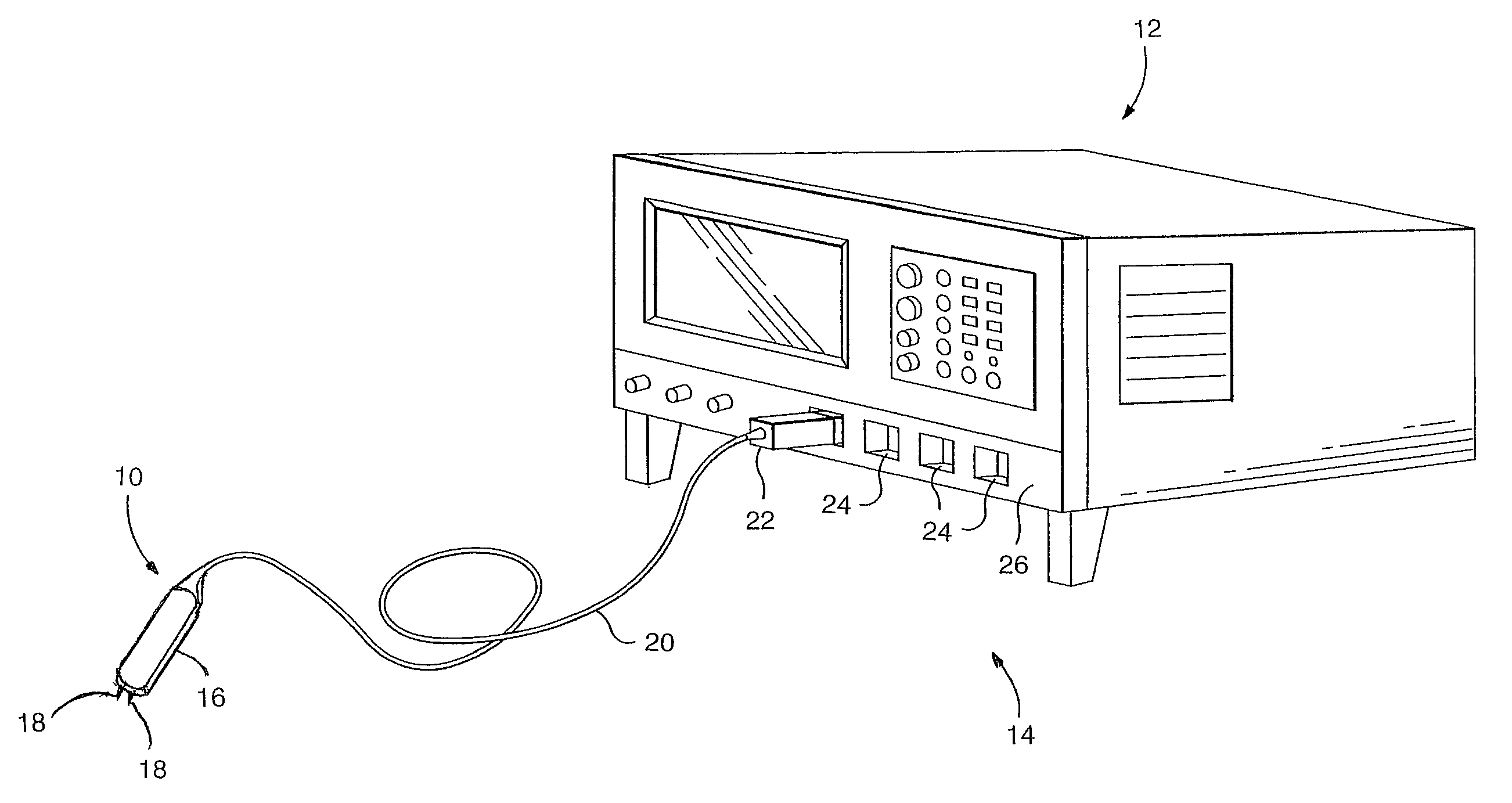
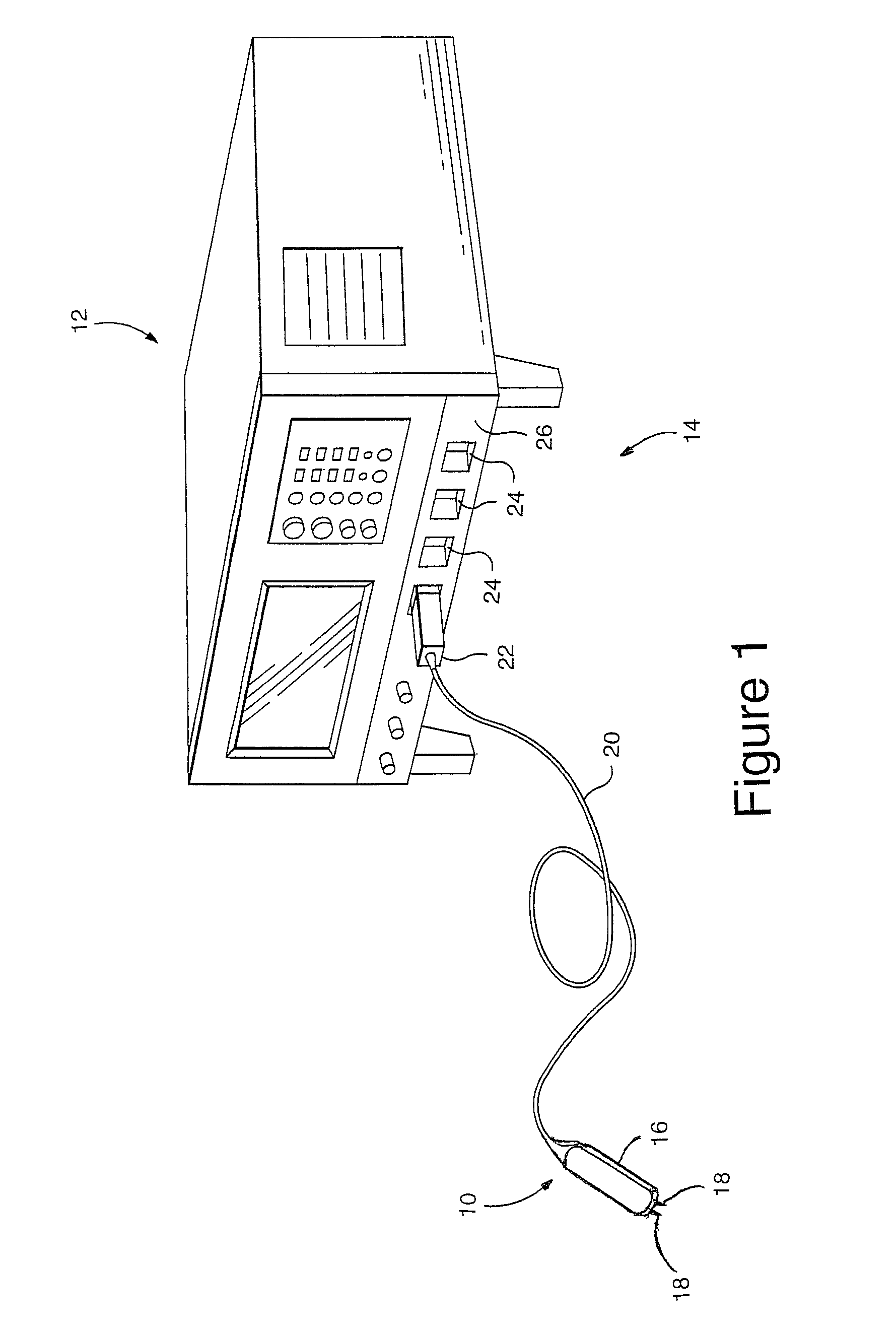
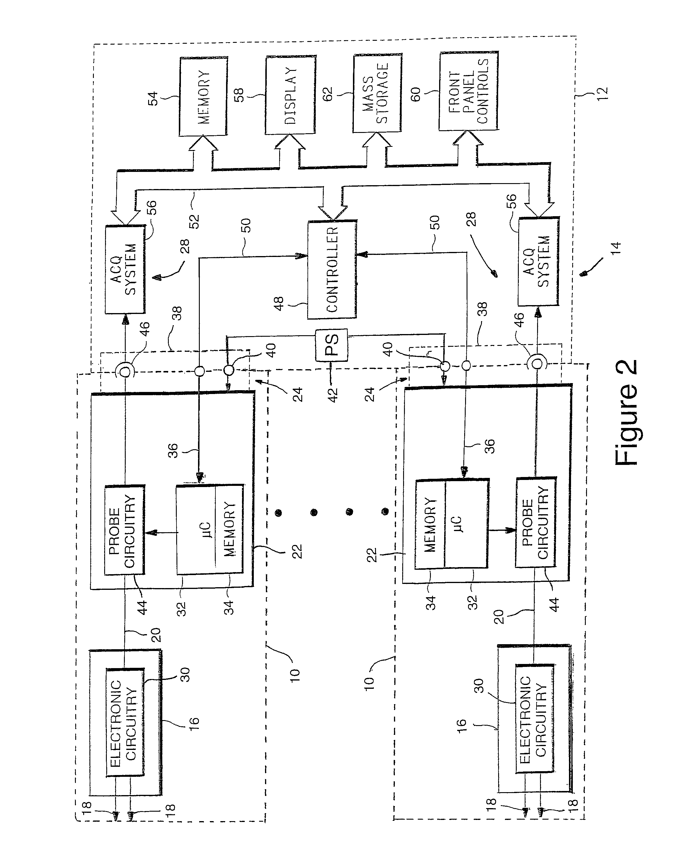
[0027]FIG. 1 illustrates a signal acquisition probe 10 connected to a signal measurement instrument 12, such as a digital oscilloscope, logic analyzer or the like, forming a signal measurement system 14 for testing a circuit or device under test. The signal acquisition probe 10 includes a housing 16, in the form of a probe head, with probing tips 18 extending from one end of the housing 16 and a signal cable 20 extending from the other end. The probing tips 18 may be signal and ground probing tips or differential probing tips. The housing may also include a single probing tip for coupling a signal under test to the probe. The housing 16 includes electrical circuitry for conditioning an electrical signal from a device under test. The signal cable 20 is coupled to a probe interconnect housing 22. The probe interconnect housing 22 has additional electronic circuitry, such as amplifiers, attenuators, filters, memory and the like, that may be controlled by a controller within the probe 1...


PUM


Abstract

A signal acquisition probe stores compressed or compressed and filtered time domain data samples representing at least one of an impulse response or step response characterizing the signal acquisition probe. The compressed or compressed and filtered time domain data samples of the impulse response or the step response are provided to a signal measurement instrument for compensating the signal measurement instrument for the impulse or step response of the signal measurement instrument.

Description

[0001]The present invention related generally to signal acquisition probes and more particularly to a signal acquisition probe storing compressed or compressed and filtered time domain data samples of an impulse response or a step response characterizing the voltage through response of the signal acquisition probe.[0002]Signal acquisition probes are designed to measure electrical signal from DC to greater than 20 GHz. They are also designed to meet specific requirements of a user, such as measuring voltage or current signals. Voltage probes are divided into passive voltage probes, active voltage probes, differential voltage probes, high voltage probes and low capacitance probes. Each type of probe has a specified bandwidth that is used with a signal measurement instrument, such as an oscilloscope, logic analyzer and the like, having a sufficiently wide bandwidth to allow accurate measurements of electrical signals from a device under test.[0003]The frequency bandwidths of a signal a...

Claims


Application Information

Patent Timeline
Patent Type & Authority Patents(United States)
IPC IPC(8): G01R25/00G01R1/067
CPCG01R1/06766
Inventor BOOMAN, RICHARD A.PICKERD, JOHN J.
Owner TEKTRONIX INC
Learn More