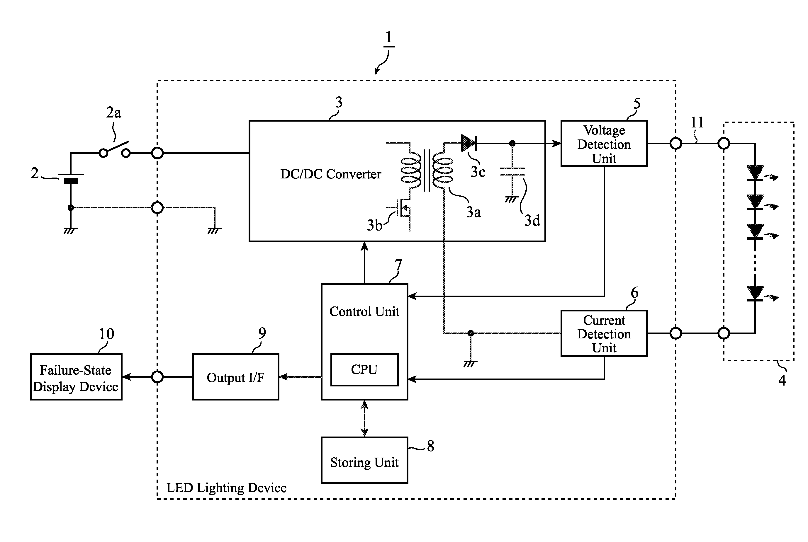
LED lighting device
a technology of led lighting and led current, which is applied in the direction of electric variable regulation, process and machine control, instruments, etc., can solve the problems of false operation, reduced light output, and inability to suppress the deterioration of the led for a short time, so as to avoid the extinction of the light and suppress the deterioration of the led
- Summary
- Abstract
- Description
- Claims
- Application Information
AI Technical Summary
Benefits of technology
Problems solved by technology
Method used
Image
Examples
embodiment 1
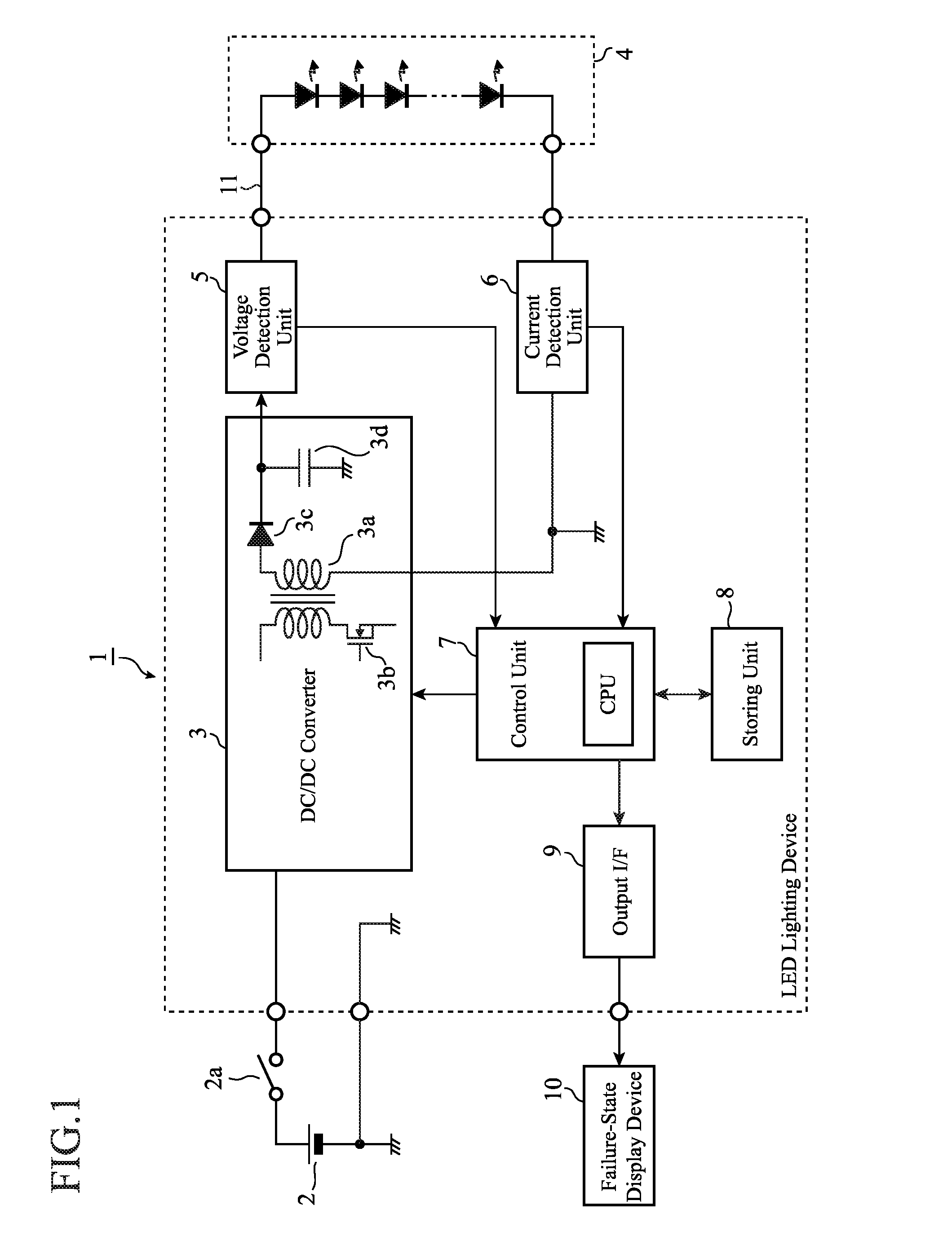
[0029]An LED lighting device 1 shown in FIG. 1 is a device for lighting an LED light source 4 by using a DC voltage from a DC power source 2, and includes a DC / DC converter 3, a voltage detection unit 5, a current detection unit 6, a control unit 7, a storing unit 8 and an output interface (hereinafter, abbreviated to “I / F”) 9. The DC power source 2 is a power source for supplying a DC voltage to the DC / DC inverter 3, and the DC voltage to the DC / DC inverter 3 is supplied or shut off by a power switch 2a. The LED light source 4 is constituted by connecting a plurality of LEDs in series and is connected to the LED lighting device 1 through a connection wiring 11. In Embodiment 1, a case where the LED light source 4 is applied to a vehicle-mounted head lamp is described by way of example. A failure-state display device 10 is what is called a telltale, and is installed inside an instrument-panel that is assembled to a dashboard.
[0030]The DC / DC converter (power source unit) 3 is constit...
embodiment 2
[0068]In the above Embodiment 1, in order to check whether the disconnection is transient or continuous, it is configured that the temporary stop and the temporary operation of the DC / DC converter 3 are repeated the predetermined number of times, whereas in Embodiment 2, it is configured that the temporary stop and temporary operation are repeated for a predetermined period of time. It is noted that since an LED lighting device of Embodiment 2 has a similar configuration in the drawing to that of the LED lighting device shown in FIG. 1, the following will be described with the aid of FIG. 1.
[0069]Next, an operation of the LED lighting device 1 according to Embodiment 2 will be described with reference to a flowchart shown in FIG. 8. Hereupon, in FIG. 8, Steps ST2 to ST7, ST10 to ST16, ST18 and ST19 are similar processes to those in FIG. 3, and hence their descriptions will be omitted; the description will be given focusing on particular Steps ST21 to ST24 in Embodiment 2.
[0070]In Em...
embodiment 3
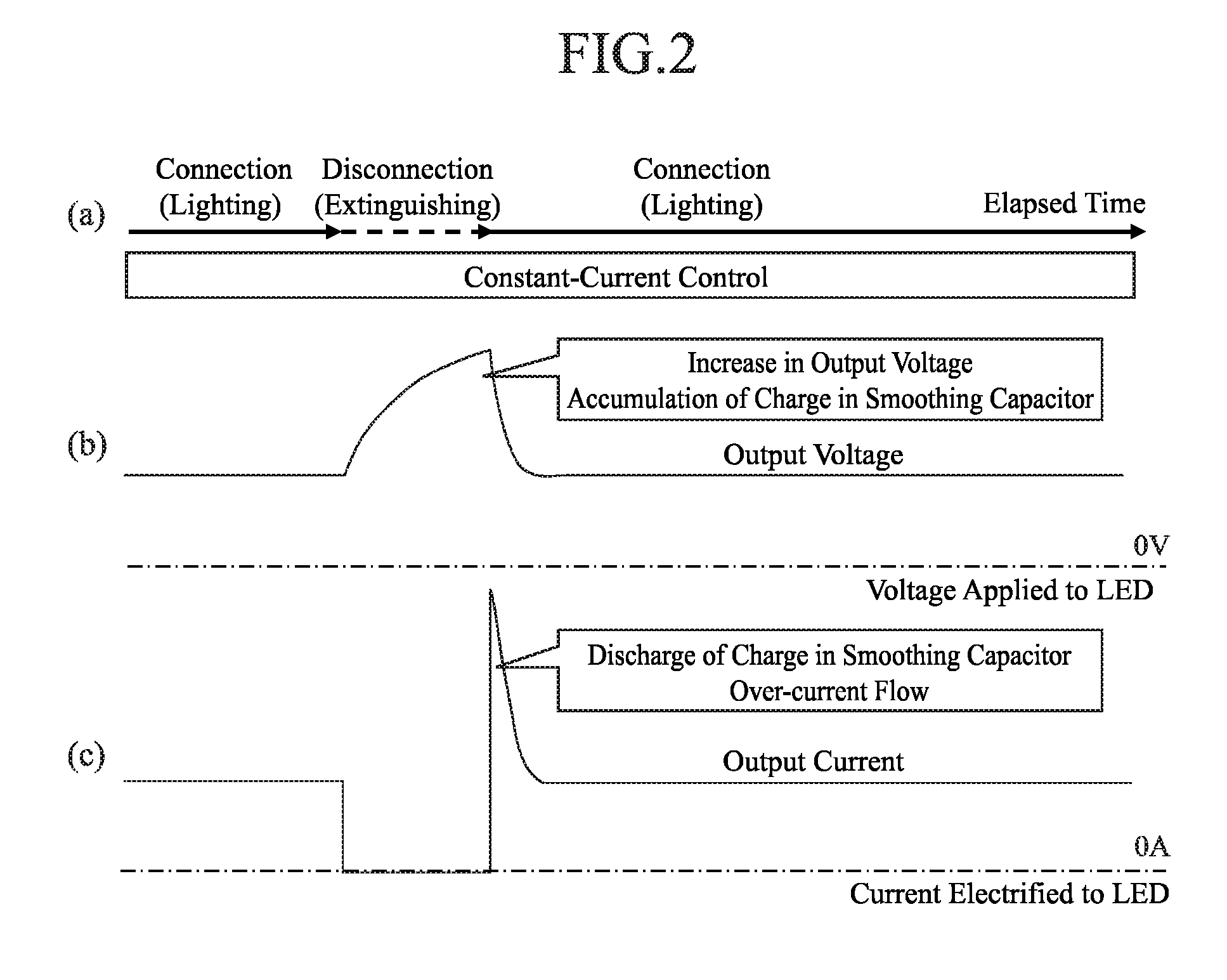
[0075]Since an LED has a constant voltage characteristic, no current is flown therein when a specific voltage is not applied thereto. Therefore, in order to carry out a conduction check of a wiring (disconnection detection process), it is necessary to apply thereto a voltage that exceeds a forward voltage of the LED. However, an application of an excessive voltage may deteriorate the LED due to an over-current at the time of the restoration of an electrification. For example, in FIG. 6, if the disconnection is restored during a first temporary operation, the over-current may be produced since a voltage higher than a set voltage is applied thereto.
[0076]Therefore, in Embodiment 3, in order to prevent the excessive voltage of the applied voltage, it is contemplated that the disconnection detection process is performed in such a manner that a voltage adding a slight margin to a voltage having been outputted in an immediately preceding normal operation is applied thereto together with a...
PUM
 Abstract
Description
Claims
Application Information
 - R&D
- Intellectual Property
- Life Sciences
- Materials
- Tech Scout
- Unparalleled Data Quality
- Higher Quality Content
- 60% Fewer Hallucinations
Browse by: Latest US Patents, China's latest patents, Technical Efficacy Thesaurus, Application Domain, Technology Topic, Popular Technical Reports.
© 2025 PatSnap. All rights reserved.Legal|Privacy policy|Modern Slavery Act Transparency Statement|Sitemap|About US| Contact US: help@patsnap.com


