
Multi-channel contaminant measurement system

Active Publication Date: 2015-09-15
EMC IP HLDG CO LLC
View PDF3 Cites 0 Cited by
  • Summary
  • Abstract
  • Description
  • Claims
  • Application Information

AI Technical Summary

Benefits of technology

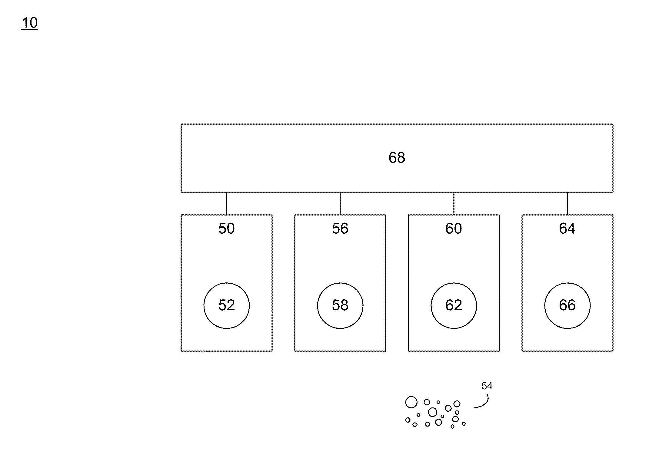
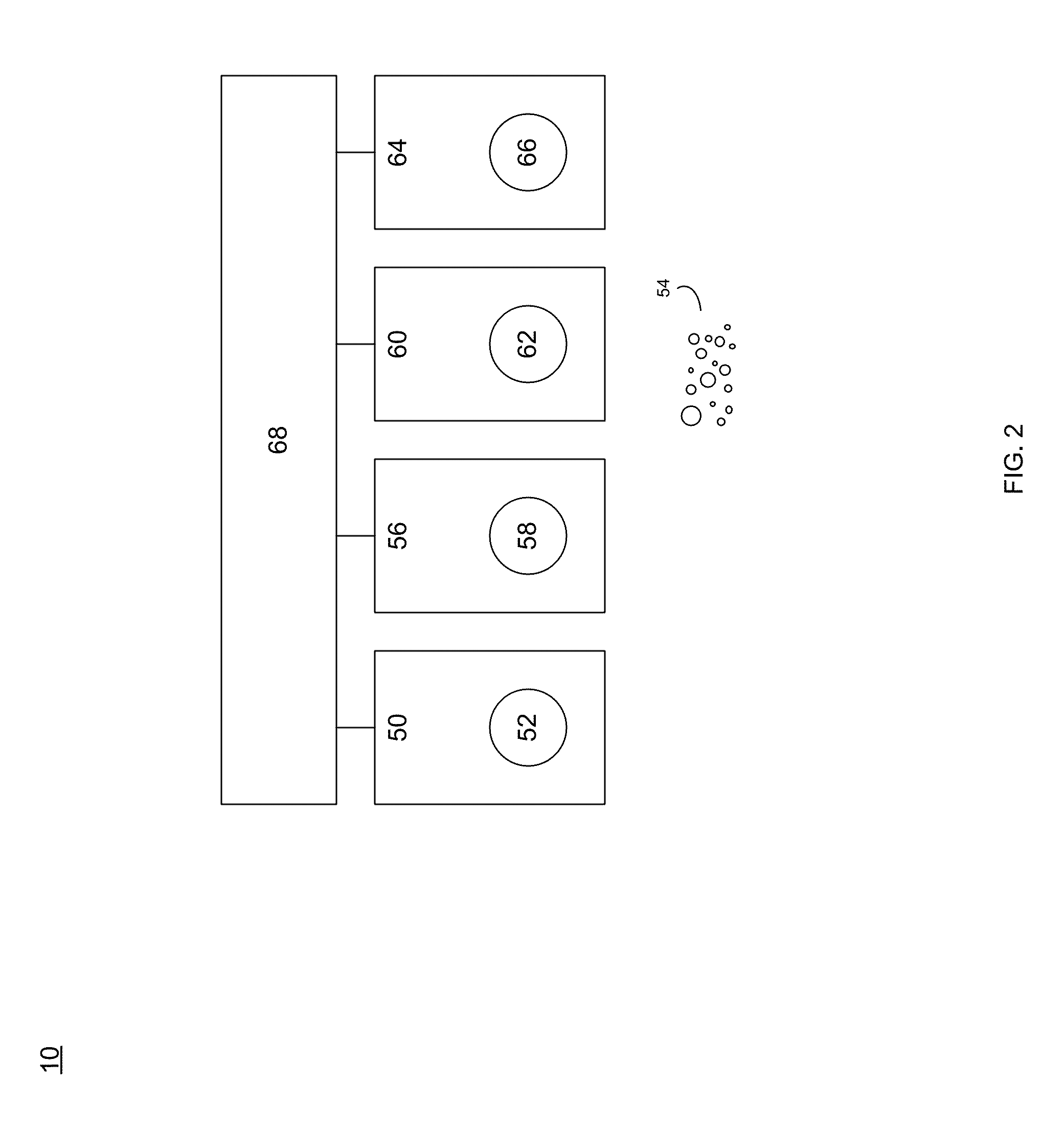
The patent describes a multi-channel contaminant sensor that can detect different airborne contaminants and their reaction with the sensor's base metal portions. The sensor includes four test platforms, each with a different base metal portion that reacts in a unique way when exposed to contaminants. An energizing circuit is used to excite the test platforms and determine changes in their resonant frequency and resistivity. The sensor can be used in various applications to detect and measure airborne contaminants.

Problems solved by technology

Unfortunately, such systems often work in harsh work environments.
For example, airborne contaminants such as chlorides, sulfides and oxides often result in the growth of corrosion on critical components (especially those made out of copper).
While various systems have been utilized to determine the presence of airborne contaminants, such systems are often incapable of identifying the particular airborne contaminant (as opposed to just indicating that an airborne contaminant is present).

Method used


Image

  • Multi-channel contaminant measurement system
  • Multi-channel contaminant measurement system
  • Multi-channel contaminant measurement system

Examples


Embodiment Construction

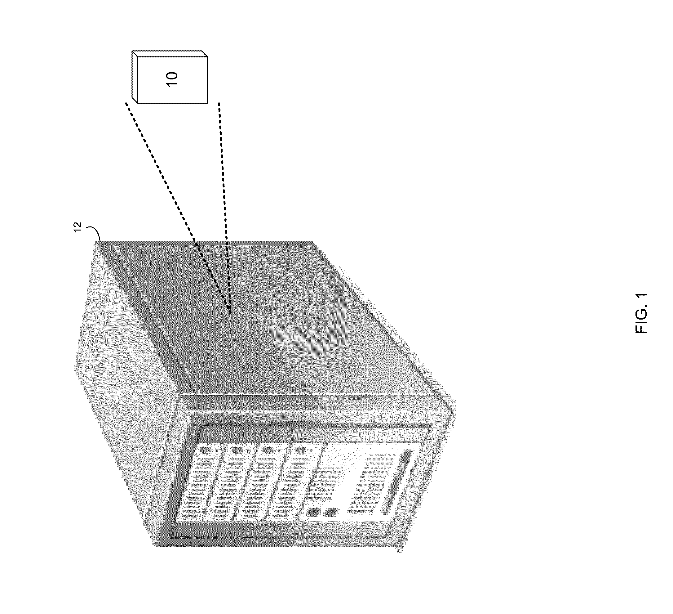
[0018]Referring to FIG. 1, there is shown multi-channel contamination measurement system 10 that may be positioned within, positioned proximate, or incorporated into IT equipment 12. For example, multi-channel contamination measurement system 10 may be positioned within or proximate one or more server computers, hosts, data arrays, switches, routers, and / or IT equipment racks.

[0019]Multi-channel contaminant measurement system 10 may be configured to determine the level of airborne contaminants present within an operating environment (e.g., an IT operating environment). For example, if multi-channel contamination measurement system 10 is incorporated into IT equipment 12, and IT equipment 12 is positioned within a server room (not shown), multi-channel contamination measurement system 10 may measure the quantity of airborne contaminants within the server room (not shown).

[0020]As multi-channel contamination measurement system 10 is a multi-channel device, multi-channel contamination ...


PUM


Abstract

A multi-channel contaminant sensor includes a first contamination test platform including an exposed first base metal portion that react in a first manner when exposed to one or more airborne contaminates. A second contamination test platform includes an exposed second base metal portion that reacts in a second manner when exposed to the one or more airborne contaminants.

Description

TECHNICAL FIELD[0001]This disclosure relates to contamination measurement systems and, more particularly, to airborne contamination measurement systems.BACKGROUND[0002]Storing electronic content is of paramount importance in modern business. Accordingly, various systems may be employed to store such electronic content. Unfortunately, such systems often work in harsh work environments. For example, airborne contaminants such as chlorides, sulfides and oxides often result in the growth of corrosion on critical components (especially those made out of copper).[0003]While various systems have been utilized to determine the presence of airborne contaminants, such systems are often incapable of identifying the particular airborne contaminant (as opposed to just indicating that an airborne contaminant is present).SUMMARY OF DISCLOSURE[0004]In a first implementation, a multi-channel contaminant sensor includes a first contamination test platform including an exposed first base metal portion...

Claims


Application Information

Patent Timeline
IPC IPC(8): G01N27/00G01N27/02G01N27/04
CPCG01N27/00G01N33/0031G01N17/02
Inventor DARIAVACH, NADER G.LIANG, JINFRENCH, FRANCIS W.CALLAHAN, PAUL T.BARR, GORDON O.
Owner EMC IP HLDG CO LLC
Learn More