Method for producing substrate with a microstructure

a microstructure and substrate technology, applied in the direction of thin material processing, instruments, coatings, etc., can solve the problems of increasing the cost expense, implementing this manufacturing process, and the requirement to control the liquid evaporation speed, so as to reduce the complexity of the manufacturing process and the required cost expense

Active Publication Date: 2015-09-15
SOUTHERN TAIWAN UNIVERSITY OF TECHNOLOGY
View PDF9 Cites 2 Cited by
  • Summary
  • Abstract
  • Description
  • Claims
  • Application Information

AI Technical Summary

Benefits of technology

[0010]Based on the problems of the prior arts, one of the objects of the present invention is to provide a substrate with a microstructure and method for producing the same. The present invention mainly utilizes a non-aqueous self-assembly method to reduce the complexity of the manufacturing process and the required cost expense.

Problems solved by technology

In other words, implementing this manufacturing process will increase the cost expense.
The drawback of this process is that it is required to control the liquid evaporation speed to reach the self-assembly purpose.
However, this is not easy to achieve in practical implementation.
Besides, the requirement of the constant-diameter microparticles is expensive in cost.
However, the drawback of this method is that a chemical layer must be generated on the surface of the substrate in advance to activate the self-assembly with the particles.
This manufacturing process is complex, time-consuming, and expensive.
However, the drawback of this method is a hydrophilic area and a hydrophobic area must be generated in advance on the surface of the substrate, such that liquid lenses can be generated on the hydrophilic area and solidified.
This manufacturing process is complex, time-consuming, and expensive.

Method used


Image

  • Method for producing substrate with a microstructure
  • Method for producing substrate with a microstructure
  • Method for producing substrate with a microstructure

Examples


Embodiment Construction

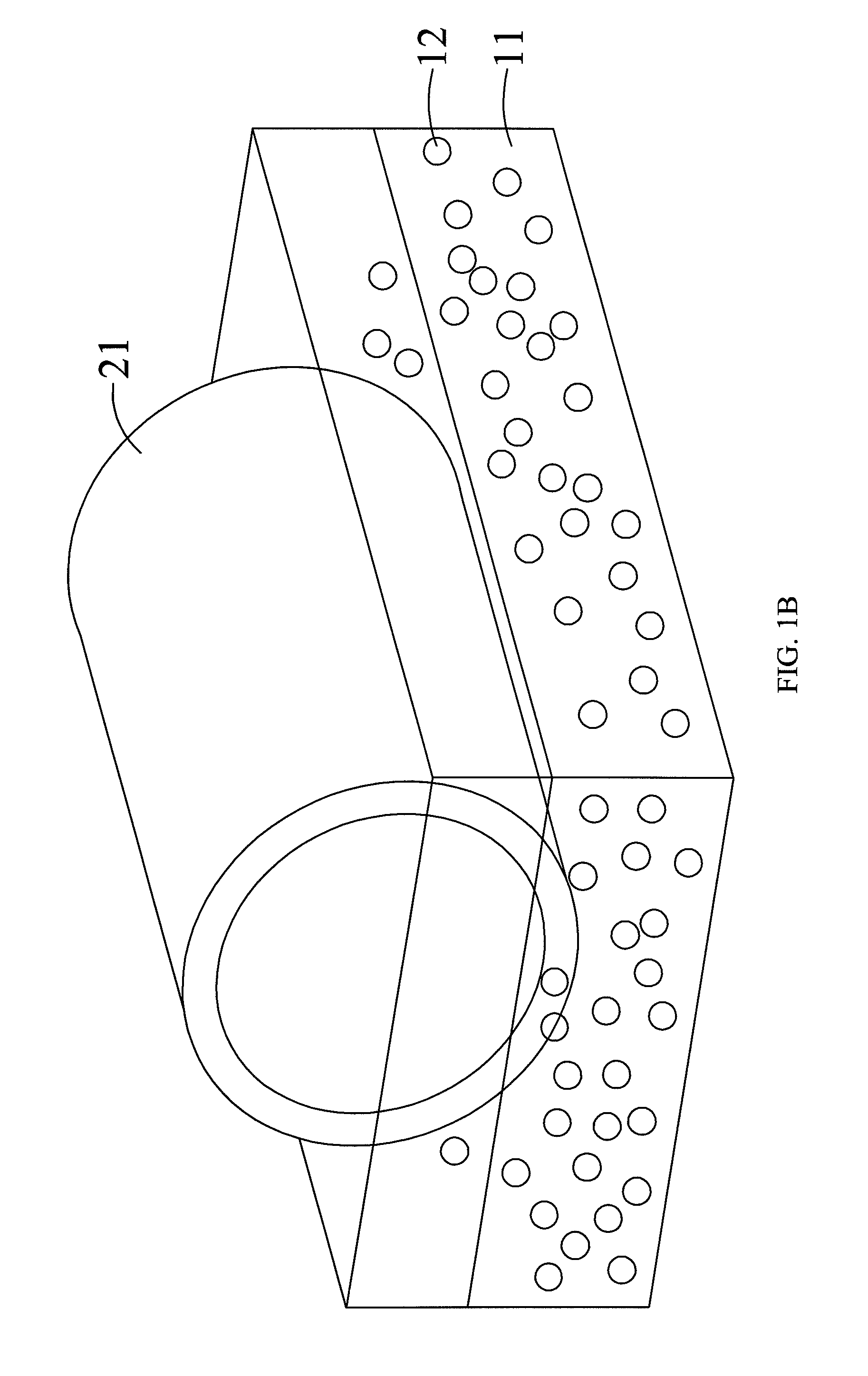
[0030]Referring to FIGS. 1A, 1B, and 7, FIG. 1A is a diagram showing a method for producing a substrate with a microstructure in a vertical stretching manner according to the preferred embodiment of the present invention, FIG. 1B is a diagram showing a method for producing a substrate with a microstructure in a horizontal rotation manner according to the preferred embodiment of the present invention, and FIG. 7 is the process diagram showing a method for manufacturing a substrate with a microstructure and method for producing the same according to the preferred embodiment of the present invention. In FIGS. 1A, 1B, and 7, the substrate with a microstructure and method for producing the same comprises the following steps: provide a mixed solution 10 and a master mold 21 in Step 50, wherein the mixed solution 10 comprises a plurality of particles 12 and an optical curing adhesive 11, and the master mold 21 is dip-coated in the mixed solution 10 such that the plurality of particles 12 a...


PUM

PropertyMeasurementUnit
sizeaaaaaaaaaa
diameteraaaaaaaaaa
separation speedaaaaaaaaaa

Abstract

Disclosed are a substrate with a microstructure and a method for producing the same. In this method microparticles of a random allocation by means of a natural self-assembly mechanism are used to coat on a master mold. Firstly, hollow micro glass particles within a specific size range are mixed with a UV-curable adhesive to become a mixed solution. Afterwards, the master mold is dip-coated in the mixed solution and the microparticles coated on the master mold are self-assembled. To fix the microparticles on the master mold to form a sphere array microstructure with a three dimensional random allocation, a UV light source is used to radiate the master mold for curing. Afterwards, an inverse mold with the corresponding microstructure is fabricated by electroforming or polydimethylsiloxane (PDMS) casting the master mold. Thus, the inverse mold can be applied to the fabrication of a substrate with the corresponding microstructure.

Description

CROSS-REFERENCE TO RELATED APPLICATION[0001]This application claims priority from Taiwan Patent Application No. 101116432, filed on May 9, 2012, the contents of which are hereby incorporated by reference in their entirety for all purposes.BACKGROUND OF THE INVENTION[0002]1. Field of the Invention[0003]The present invention relates to a substrate with a microstructure and method for producing the same, and particularly, a substrate with a microstructure and method for producing the same by using a non-aqueous self-assembly process.[0004]2. Description of the Related Art[0005]Self-assembly is a microscopic phenomenon existed in nature. This begins with the permeation of a plurality of micro- / nano-particles into an aqueous solution. Evaporation of the solution will cause the liquid level of the aqueous solution to lower down, thus the mutually interactive forces of the particles force them to aggregate and align with each other. This is the self-assembly happened naturally.[0006]Genera...

Claims


Application Information

Patent Timeline
Patent Type & Authority Patents(United States)
IPC IPC(8): B29C41/14G03F7/00B29C33/38B29C33/42
CPCB29C41/14B29C33/3878G03F7/0002B29C33/424Y10T428/24479
Inventor CHUANG, CHENG-HSINCHEN, MING-YU
Owner SOUTHERN TAIWAN UNIVERSITY OF TECHNOLOGY
Why Eureka
Try Eureka