Eureka AIR delivers breakthrough ideas for toughest innovation challenges, trusted by R&D personnel around the world.

High capacity fiber-optic integrated transmission and switching systems

a high-capacity, transmission and switching technology, applied in the field of fiber optic systems and methods, can solve the problems of increasing the overall network cost and complexity, difficult to ignore the benefits of the technology, and expensive and power-hungry transmitter and receiver hardwar

Active Publication Date: 2015-09-01
CIENA
View PDF37 Cites 41 Cited by
  • Summary
  • Abstract
  • Description
  • Claims
  • Application Information

AI Technical Summary

Benefits of technology

The patent describes a reconfigurable electrical add / drop multiplexing node that includes multiple optoelectronic circuits with transmitter and receiver sections. The switch fabric is designed to perform flow switching on the full signal level between the sections with subrate grooving of the full signal performed in a separate device. The transmitter sections have N channels at a wavelength within the transparency spectrum of optical fiber, and the receiver sections optically receive each channel and provide corresponding electrical signals. The switching fabric can include an electrical cross point switch and can perform limited overhead processing without forward error correction coding. The network can also include optical circulators and optical circulation matrices for interleaving the N channels for bidirectional transmission over a single fiber. The technical effects of the patent include improved flexibility and efficiency in optical networks.

Problems solved by technology

Indeed, EDFA and Raman provide excellent, inexpensive, and low-noise optical amplification and their benefits are hard to ignore.
Accordingly, conventional solutions to capacity problem focus on expensive and power-hungry transmitter and receiver hardware, frequently requiring a combination of both EDFA and Raman amplification to lower optical noise figure, and may require new fiber types such as ultra-low loss and high effective area fibers.
All of these increase overall network cost and complexity.
When additional requirements of dynamic provisioning, protection, restoration, etc. are added, the OADM nodes become more complex and difficult to control for analog optical signals.

Method used


Image

  • High capacity fiber-optic integrated transmission and switching systems
  • High capacity fiber-optic integrated transmission and switching systems
  • High capacity fiber-optic integrated transmission and switching systems

Examples


Embodiment Construction

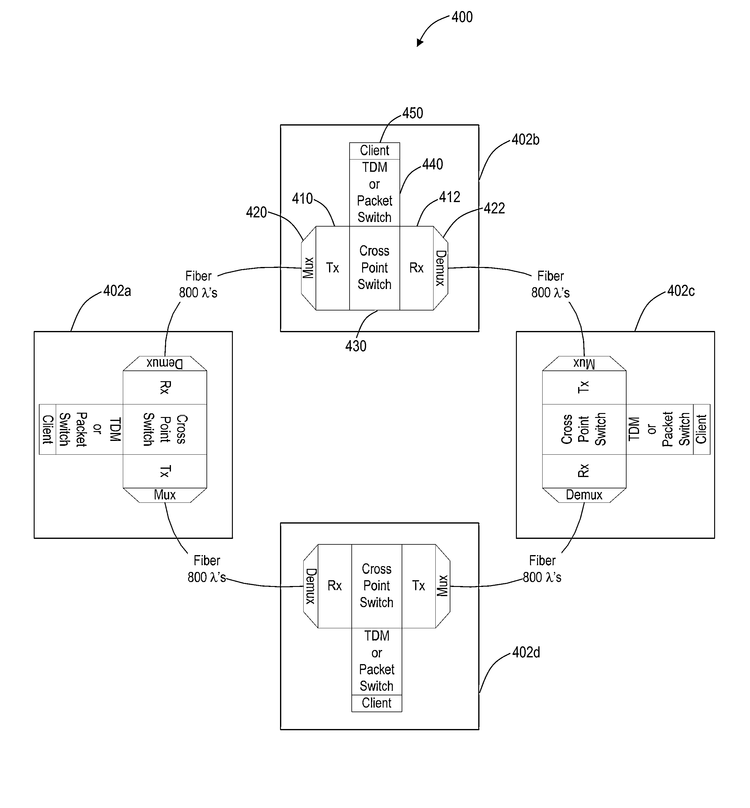
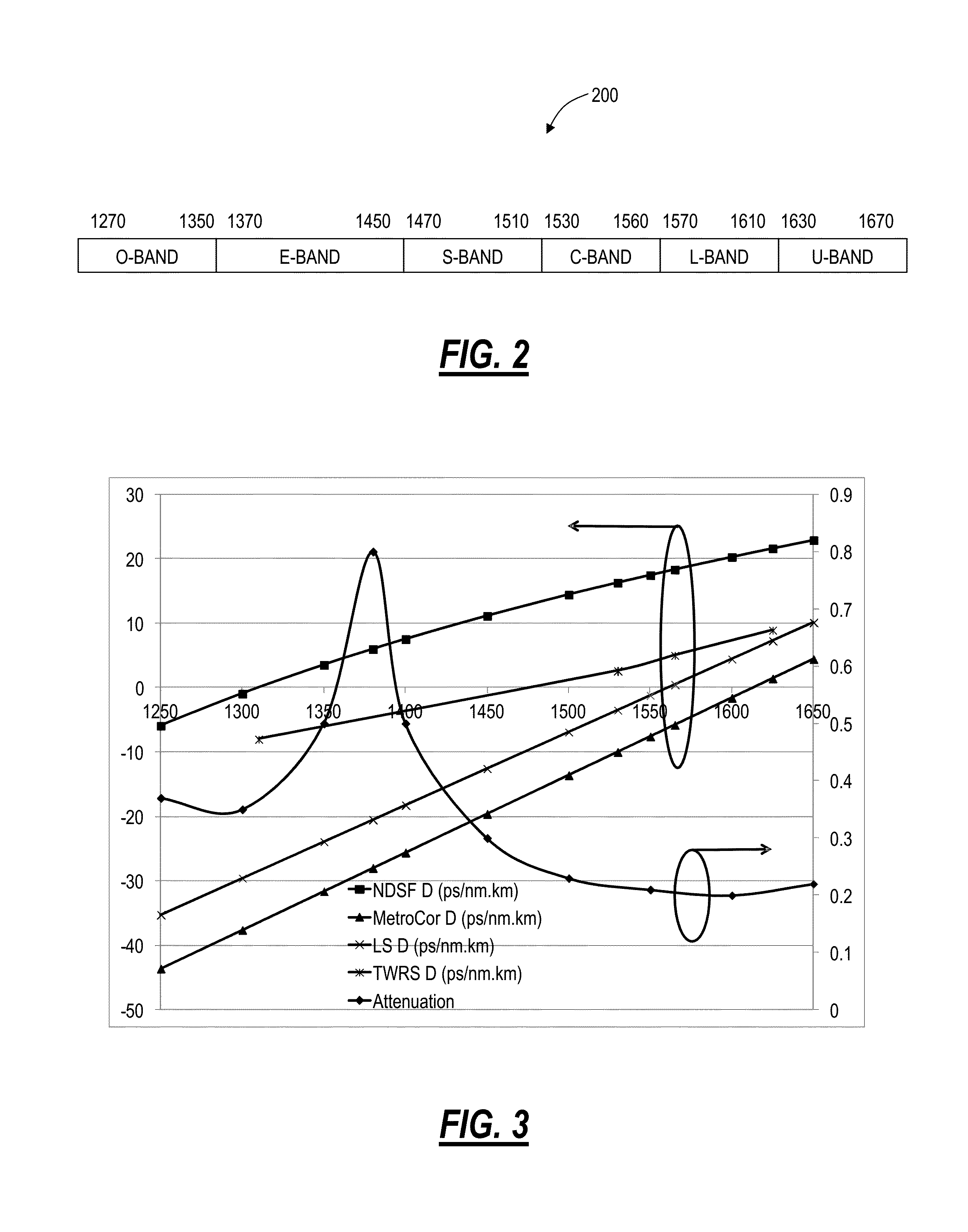
[0033]In various exemplary embodiments, novel high capacity fiber-optic integrated transmission and switching systems are described. In an exemplary embodiment, a baseline target capacity is 32 Tbps, and may be achieved with a variety of approaches as described herein. The objective is an overall system design that is low cost in high volumes, with low power consumption, and is easy to deploy and maintain. The approach uses the full “transparency” window of modern optical fibers from about 1270 nm to about 1670 nm, and populating this window with a large number of relatively low-rate wavelengths. The target span length coverage is approximately 80 km of standard non-dispersion shifted fiber (NDSF) and non-zero-dispersion shifted fiber (NZDSF), which sets a boundary condition for Loss and Chromatic Dispersion. Since optical channels are electrically terminated at every node, an electrical switching fabric is provided for both Add / Drop channel access, and for express traffic through t...


PUM


Abstract

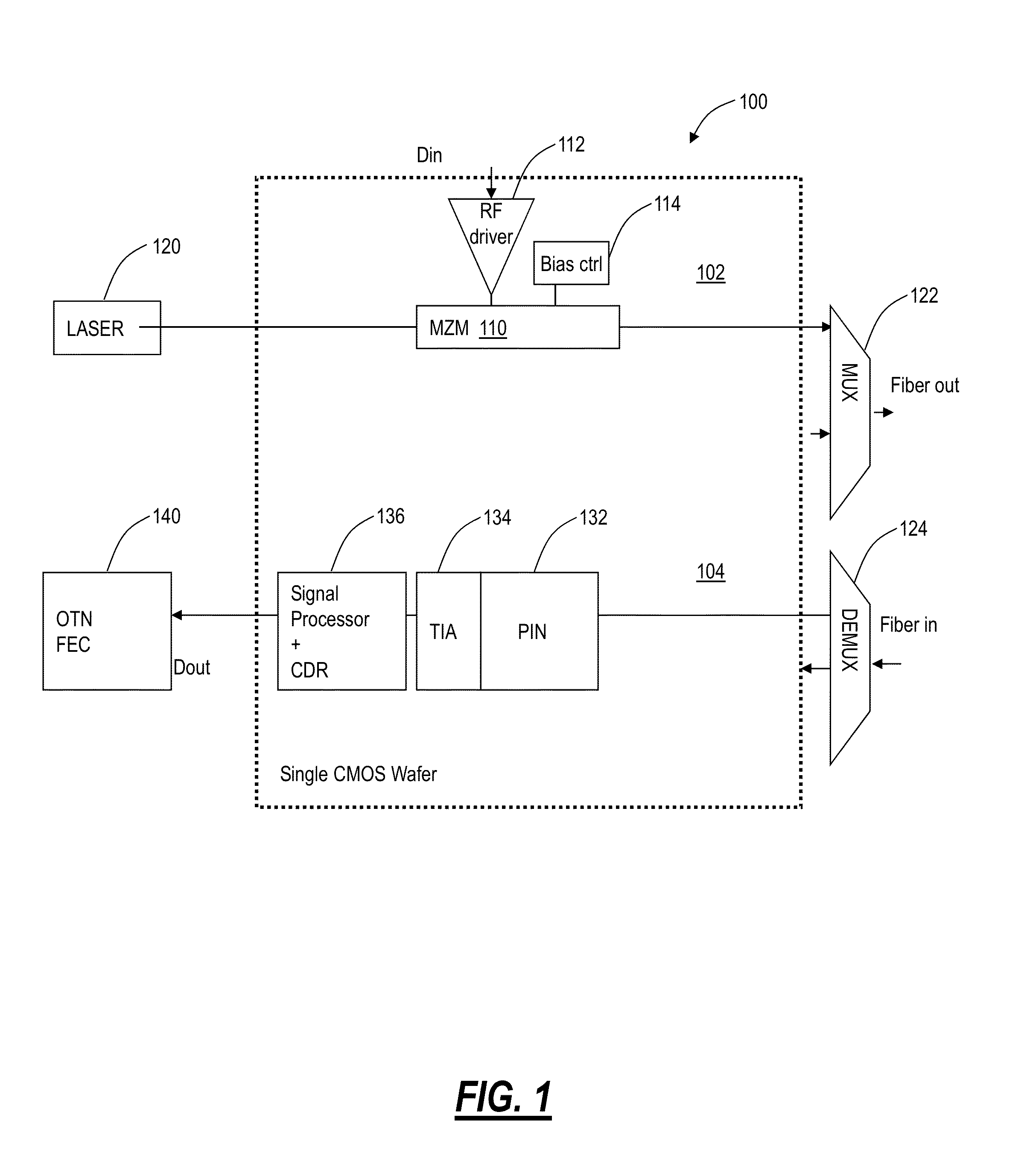
A reconfigurable electrical add / drop multiplexing node, a network, and optoelectronic integrated circuit form a novel high capacity fiber-optic integrated transmission and switching system with a baseline target capacity in excess of 1 Tbps. The node, network, and circuit can leverage optoelectronic integration of transmission and switching components along with using the full “transparency” window of modern optical fibers from about 1270 nm to about 1670 nm for a large number of relatively low-rate wavelengths. The electrical switching fabric can be part of a Reconfigurable Electrical Add / Drop Multiplexer (READM) with similar functionality as a Reconfigurable Optical Add / Drop Multiplexer (ROADM) except in a highly integrated fashion with the transmission components. The electrical switching fabric can implement flow switching on a composite signal to provide comparable functionality to optical components in electrical circuitry such as in Complementary metal-oxide-semiconductors.

Description

CROSS-REFERENCE TO RELATED APPLICATIONS[0001]This application is a continuation-in-part of co-pending U.S. patent application Ser. No. 12 / 889,158 filed Sep. 23, 2010, and entitled “HIGH-SPEED OPTICAL TRANSPONDER SYSTEMS,” the contents of which are incorporated in full by reference herein.FIELD OF THE INVENTION[0002]Generally, the field of art of the present disclosure pertains to fiber optic systems and methods, and more particularly, to high-capacity fiber-optic integrated transmission and switching systems.BACKGROUND OF THE INVENTION[0003]Fiber-optic communication networks are experiencing rapidly increasing growth in capacity. This capacity growth is reflected by individual channel data rates scaling from 10 Gbps (gigabits per second), to 40 Gbps, to developing 100 Gbps, and to future projections of 1000 Gbps channels and higher. The capacity growth is also reflected by increasing total channel count carried within an optical fiber. Conventional solutions focus almost exclusively...

Claims


Application Information

Patent Timeline
IPC IPC(8): H04J14/02H04J14/06
CPCH04J14/0212H04J14/06H04J3/1605H04J14/02H04J14/0221H04J14/0227H04J14/0273H04J14/0279H04L1/0045H04B10/40H04B10/506H04L1/0053H04J14/021H04Q11/0005H04Q2011/0016H04Q2011/0033H04Q2011/0049H04Q2011/0058
Inventor FRANKEL, MICHAEL Y.MATEOSKY, JOHN P.SHAHINE, MICHAEL H.BERTHOLD, JOSEPH
Owner CIENA
Why Eureka
Eureka Blog
Learn More