
User equipment apparatus for transmitting a plurality of signals simultaneously using at least two wireless communication schemes and method thereof

a user equipment and wireless communication technology, applied in the field of user equipment, can solve the problems of difficult and inconvenient fine unit measurement of power value, generating unnecessary power backoff, and difficult and efficient application of elaborate and precise power backoff, so as to prevent unnecessary power backoff and accurately and efficiently determine the power back-off quantity

Inactive Publication Date: 2015-08-11
LG ELECTRONICS INC
View PDF19 Cites 6 Cited by
  • Summary
  • Abstract
  • Description
  • Claims
  • Application Information

AI Technical Summary

Benefits of technology

Enables accurate and efficient power control, preventing SAR violations and reducing unnecessary power backoff, allowing for simultaneous transmission of signals using different wireless communication schemes while meeting SAR regulations.

Problems solved by technology

Hence, this contradiction causes a problem that application of an elaborate and precise power backoff is difficult.
Moreover, when a range is determined with a sufficient margin, it causes another problem that an unnecessary power backoff is generated.
Moreover, it is difficult and inconvenient to measure a power value by a fine unit.
Moreover, a method of measuring a transmission power of a first wireless communication chip and a method of delivering the measured transmission power to a second wireless communication chip have not been proposed in detail so far.
Yet, if it is impossible to perform initial transmission power estimation in a situation that open-loop power control is performed like RACH state, it causes a serious problem that the SAR is not met.
And, a solution of this problem has not been proposed at all.

Method used


Image

  • User equipment apparatus for transmitting a plurality of signals simultaneously using at least two wireless communication schemes and method thereof
  • User equipment apparatus for transmitting a plurality of signals simultaneously using at least two wireless communication schemes and method thereof
  • User equipment apparatus for transmitting a plurality of signals simultaneously using at least two wireless communication schemes and method thereof

Examples


Embodiment Construction

[0056]Reference will now be made in detail to the preferred embodiments of the present invention, examples of which are illustrated in the accompanying drawings. In the following detailed description, the invention includes details to help the full understanding of the present invention. Yet, it is apparent to those skilled in the art that the present invention can be implemented without these details.

[0057]Occasionally, to prevent the present invention from getting vaguer, structures and / or devices known to the public are skipped or can be represented as block diagrams centering on the core functions of the structures and / or devices. Wherever possible, the same reference numbers will be used throughout the drawings to refer to the same or like parts.

[0058]In the description of the present invention, a user equipment (UE) designates a mobile or fixed type communication device used by a user, such as a mobile station (MS), an advanced mobile station (AMS), mobile terminal and a mobil...


PUM


Abstract

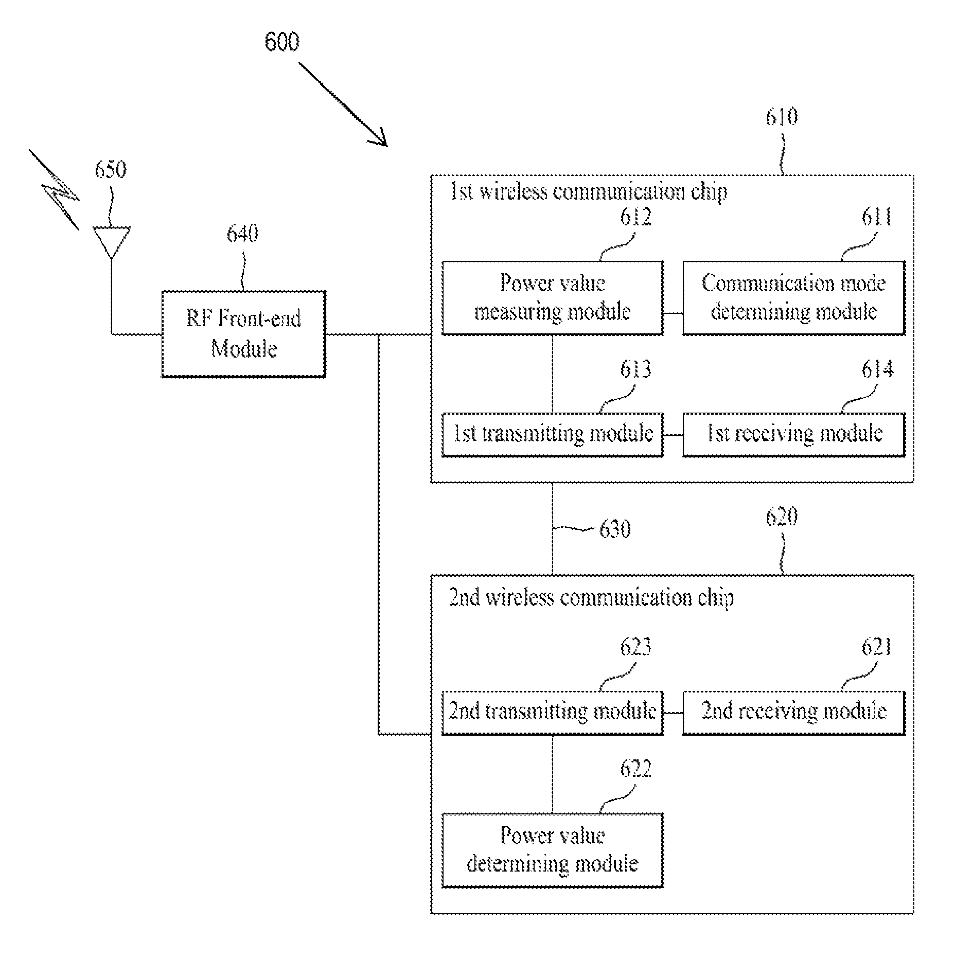
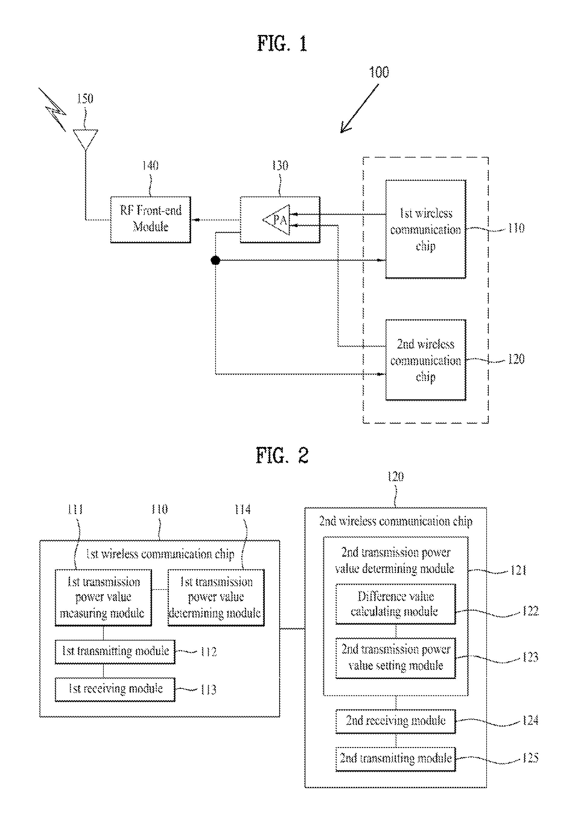
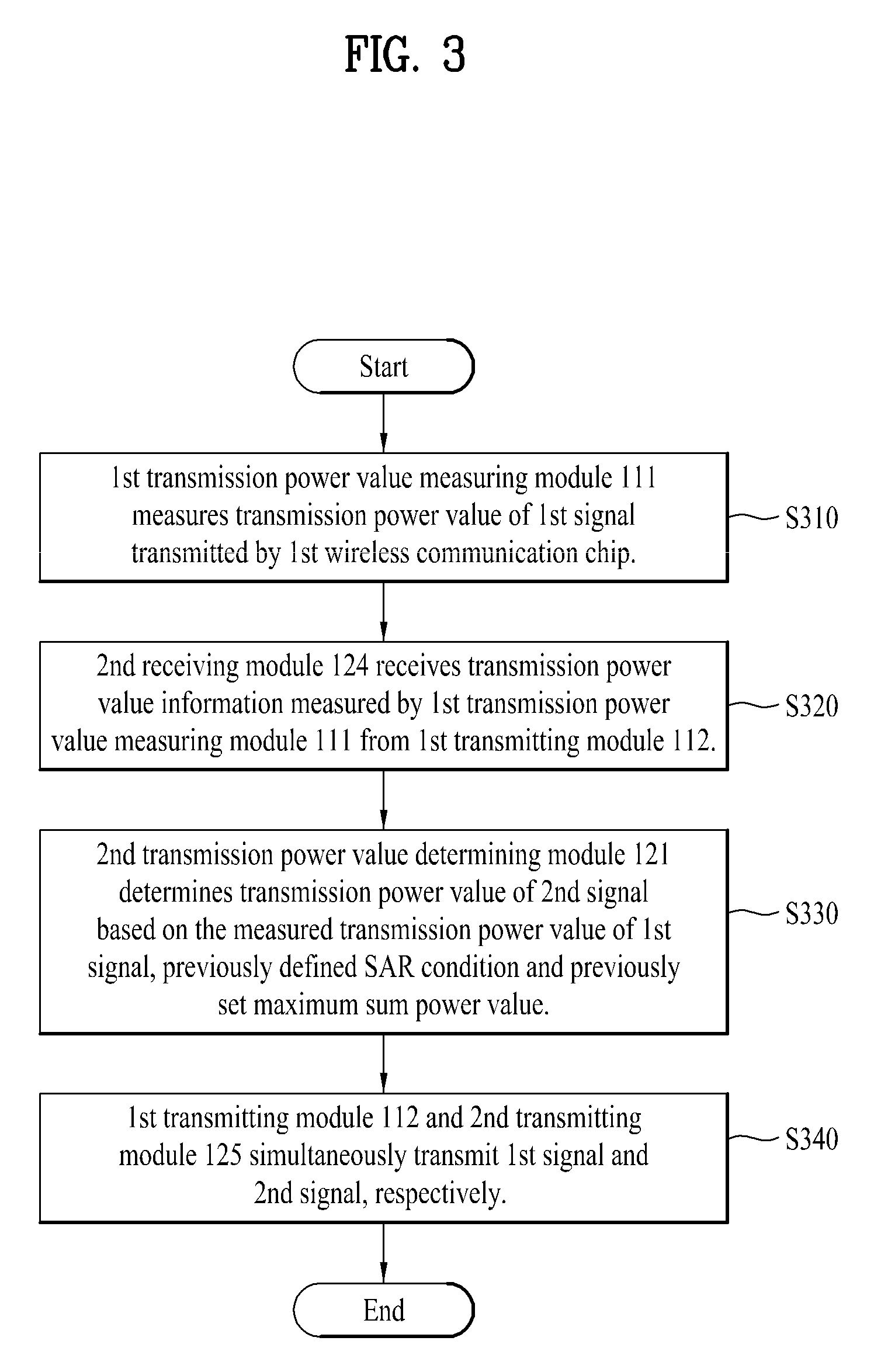
A user equipment (UE) of a wireless communication system is disclosed. A second receiving module, of a second wireless communication chip, is configured for receiving a transmission power value of a first signal configured to be transmitted from a first wireless communication chip of the UE. A second transmission power value determining module, of the second wireless communication chip, is configured for determining a transmission power value of a second signal configured to be transmitted from the second wireless communication chip, the determination based on the received transmission power value of the first signal and a predefined specific absorption rate (SAR) condition, wherein the first wireless communication chip is configured for transmitting the first signal using a first wireless communication scheme, wherein the second wireless communication chip is configured for transmitting the second signal using a second wireless communication scheme simultaneously with the transmission of the first signal by the first wireless communication chip.

Description

CROSS-REFERENCE TO RELATED APPLICATIONS[0001]Pursuant to 35 U.S.C. §119, this application claims the benefit of earlier filing date and right of priority to Korean Application Nos. 10-2010-0111050, filed on Nov. 9, 2010, 10-2010-0111049, filed on Nov. 9, 2010, and 10-2010-0107343, filed on Oct. 29, 2010, and also claims the benefit of U.S. Provisional Application Ser. No. 61 / 359,810, filed on Jun. 29, 2010, the contents of which are hereby incorporated by reference herein in their entireties.BACKGROUND OF THE INVENTION[0002]1. Field of the Invention[0003]The present invention relates to a user equipment (UE), and more particularly, to a user equipment apparatus for transmitting a plurality of signals simultaneously using at least two wireless communication schemes and method thereof.[0004]2. Discussion of the Related Art[0005]Recently, the demand for a use of radio waves keeps increasing owing to the remarkable development of the wireless communication technology. And, the radio wav...

Claims


Application Information

Patent Timeline
Patent Type & Authority Patents(United States)
IPC IPC(8): H04B7/00H04W52/16
CPCH04W52/16H04W52/346H04W52/146H04W52/367H04W52/38
Inventor KWUN, SOONIKKIM, INKYUNGPARK, JAEHYUNYEOM, JAESUNGWHANG, YONGNAM
Owner LG ELECTRONICS INC
Learn More