
Method and device for decoding an audio soundfield representation for audio playback

a soundfield representation and audio technology, applied in the field of audio soundfield representation for audio playback, can solve the problems of difficult to obtain the inverse and wrong audio reproduction

Active Publication Date: 2015-08-04
DOLBY LAB LICENSING CORP
View PDF18 Cites 49 Cited by
  • Summary
  • Abstract
  • Description
  • Claims
  • Application Information

AI Technical Summary

Benefits of technology

[0013]An advantage of the invention is that no parametric description of the sound sources is required; instead, a soundfield description such as Ambisonics can be used.
[0014]According to the invention, a method for decoding an audio soundfield representation for audio playback comprises steps of steps of calculating, for each of a plurality of loudspeakers, a panning function using a geometrical method based on the positions of the loudspeakers and a plurality of source directions, calculating a mode matrix from the source directions, calculating a pseudo-inverse mode matrix of the mode matrix, and decoding the audio soundfield representation, wherein the decoding is based on a decode matrix that is obtained from at least the panning function and the pseudo-inverse mode matrix.
[0015]According to another aspect, a device for decoding an audio soundfield representation for audio playback comprises first calculating means for calculating, for each of a plurality of loudspeakers, a panning function using a geometrical method based on the positions of the loudspeakers and a plurality of source directions, second calculating means for calculating a mode matrix from the source directions, third calculating means for calculating a pseudo-inverse mode matrix of the mode matrix, and decoder means for decoding the soundfield representation, wherein the decoding is based on a decode matrix and the decoder means uses at least the panning function and the pseudo-inverse mode matrix to obtain the decode matrix. The first, second and third calculating means can be a single processor or two or more separate processors.
[0016]According to yet another aspect, a computer readable medium has stored on it executable instructions to cause a computer to perform a method for decoding an audio soundfield representation for audio playback comprises steps of calculating, for each of a plurality of loudspeakers, a panning function using a geometrical method based on the positions of the loudspeakers and a plurality of source directions, calculating a mode matrix from the source directions, calculating pseudo-inverse of the mode matrix, and decoding the audio soundfield representation, wherein the decoding is based on a decode matrix that is obtained from at least the panning function and the pseudo-inverse mode matrix.
[0017]Advantageous embodiments of the invention are disclosed in the dependent claims, the following description and the FIGS.

Problems solved by technology

Another problem occurs in that the inverse of the mode matrix (that represents the loudspeaker setup) is required.
However, the exact inverse is difficult to obtain, which also leads to wrong audio reproduction.

Method used


Image

  • Method and device for decoding an audio soundfield representation for audio playback
  • Method and device for decoding an audio soundfield representation for audio playback
  • Method and device for decoding an audio soundfield representation for audio playback

Examples


Embodiment Construction

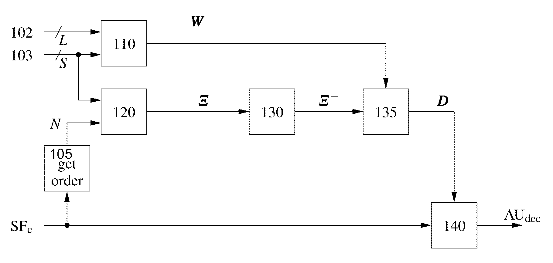
[0026]As shown in FIG. 1, a method for decoding an audio soundfield representation SFc for audio playback comprises steps of calculating 110, for each of a plurality of loudspeakers, a panning function W using a geometrical method based on the positions 102 of the loudspeakers (L is the number of loudspeakers) and a plurality of source directions 103 (S is the number of source directions), calculating 120 a mode matrix Ξ from the source directions and a given order N of the soundfield representation, calculating 130 a pseudo-inverse mode matrix Ξ+ of the mode matrix Ξ, and decoding 135,140 the audio soundfield representation SFc, wherein decoded sound data AUdec are obtained. The decoding is based on a decode matrix D that is obtained 135 from at least the panning function W and the pseudo-inverse mode matrix Ξ+. In one embodiment, the pseudo-inverse mode matrix is obtained according to Ξ+=ΞH[ΞΞH]−1. The order N of the soundfield representation may be pre-defined, or it may be extra...


PUM


Abstract

Soundfield signals as such e.g. Ambisonics carry a representation of a desired sound field. The Ambisonics format is based on spherical harmonic decomposition of the soundfield, and Higher Order Ambisonics uses spherical harmonics of at least 2nd order. However, commonly used loudspeaker setups are irregular and lead to problems in decoder design. A method for improved decoding an audio soundfield representation for audio playback comprises calculating a panning function using a geometrical method based on the positions of a plurality of loudspeakers and a plurality of source directions, calculating a mode matrix Ξ from the loudspeaker positions, calculating a pseudo-inverse mode matrix μ+ and decoding the audio soundfield representation. The decoding is based on a decode matrix that is obtained from the panning function and the pseudo-inverse mode matrix Ξ+.

Description

[0001]This application claims the benefit, under 35 U.S.C. §365 of International Application PCT / EP2011 / 054644, filed Mar. 25, 2011, which was published accordance with PCT Article 21(2) on Sep. 29, 2011 in English and which claims the benefit of European patent application No. 10305316.1, filed Mar. 26, 2010.FIELD OF THE INVENTION[0002]This invention relates to a method and a device for decoding an audio soundfield representation, and in particular an Ambisonics formatted audio representation, for audio playback.BACKGROUND[0003]This section is intended to introduce the reader to various aspects of art, which may be related to various aspects of the present invention that are described and / or claimed below. This discussion is believed to be helpful in providing the reader with background information to facilitate a better understanding of the various aspects of the present invention. Accordingly, it should be understood that these statements are to be read in this light, and not as ...

Claims


Application Information

Patent Timeline
Patent Type & Authority Patents(United States)
IPC IPC(8): H04R5/00H04S3/02G10L19/008
CPCG10L19/008H04S3/02H04S2420/11H04S7/308H04S2400/13
Inventor BATKE, JOHANN-MARKUSKEILER, FLORIANBOEHM, JOHANNES
Owner DOLBY LAB LICENSING CORP
Learn More