
Image recording system, image rewriting system, and image recording method

a recording system and image technology, applied in the field of image recording system, image rewriting system, image recording method, can solve the problem that the quality of scan image to be recorded on the recording medium might be poorer than the level readable by a reading device, and achieve the effect of matching or excelling the level readabl

Inactive Publication Date: 2015-07-28
RICOH KK
View PDF12 Cites 4 Cited by
  • Summary
  • Abstract
  • Description
  • Claims
  • Application Information

AI Technical Summary

Benefits of technology

The patent aims to ensure that the quality of a scan image is as good as the recording medium can handle. This means that the image will be of high quality and can be easily read by the recording medium.

Problems solved by technology

However, with the technique disclosed in JP-A No. 2008-194905, the quality of a scan image to be recorded on the recording medium might be poorer than a level readable by a reading device.

Method used


Image

  • Image recording system, image rewriting system, and image recording method
  • Image recording system, image rewriting system, and image recording method
  • Image recording system, image rewriting system, and image recording method

Examples


examples

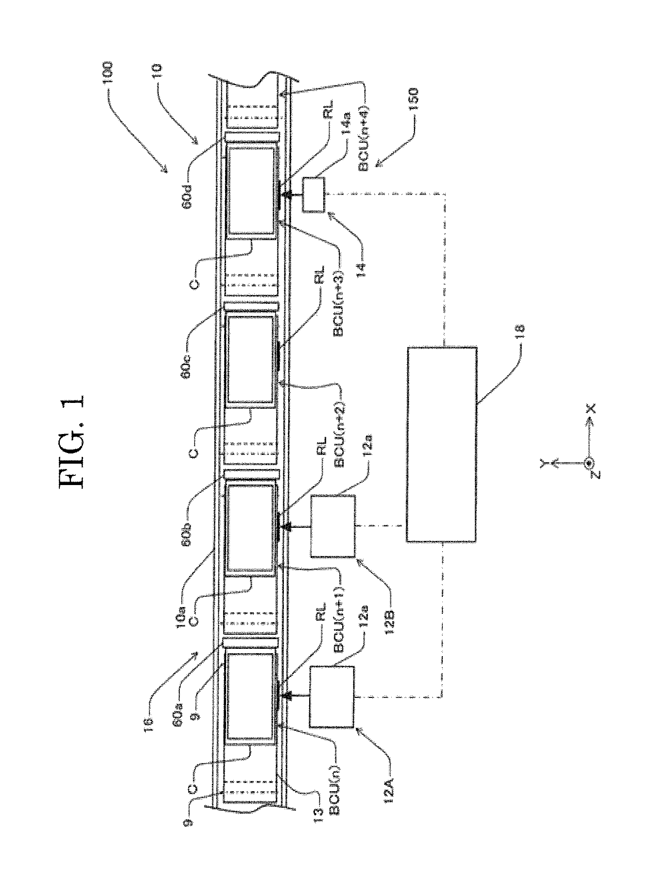
[0197]Specific examples will be explained below. Here, a container C (ORICON 32B manufactured by Sanko Co., Ltd.) was conveyed by the conveyor device 10 having a conveying speed of 100 mm / second, and the container C was decelerated with a predetermined position on the conveyor device 10 (a position precisely facing the recording device 14) observed as a target stop position. A relationship under these conditions, among a time taken for recording to the container to be started after the container C reached the target stop position, the maximum value of the amplitude of vibration in the X axis direction (conveying direction), and the readability of the barcode (INTERLEAVED TWO OF FIVE, 10 digits, width of thin bars of 0.25 mm, 0.375 mm, and 0.5 mm) is shown in Table 1 to Table 6. The relationship shown in Table 1 to Table 6 is also shown in FIG. 14 to FIG. 16. In FIG. 14 to FIG. 16, symbol I indicates a comprehensive grade of C (readable), symbol II indicates a comprehensive grade of ...

example 25

[0237]In Example 25, an image shown in FIG. 17 including a barcode was recorded in the writing order indicated by (1) to (7) in FIG. 19, so that the barcode may be recorded within the latter half (e.g., from 0.62 s to 0.83 s) of the recording time (with a length of 0.83 s) of the image. Reading (scanning) of the recorded barcode was performed a hundred times with the barcode scanner mentioned above, which resulted in 97 times of successful reading. The time slot in which to record the barcode is not limited to the time slot mentioned above, but may be an arbitrary time slot within the latter half of from 0.415 s to 0.83 s of the recording time (with a length of 0.83 s).

example 26

[0238]In Example 26, the image shown in FIG. 17 including a barcode was recorded on a RL in the writing order indicated by (1) to (7) in FIG. 20, so that the barcode may be recorded within the latter half (e.g., from 0.53 s to 0.74 s) of the recording time (with a length of 0.83 s) of the image. Reading (scanning) of the recorded barcode was performed a hundred times with the barcode scanner mentioned above, which resulted in 98 times of successful reading. The time slot in which to record the barcode is not limited to the time slot mentioned above, but may be an arbitrary time slot within the later half of from 0.415 s to 0.83 s) of the recording time (with a length of 0.83 s).


PUM


Abstract

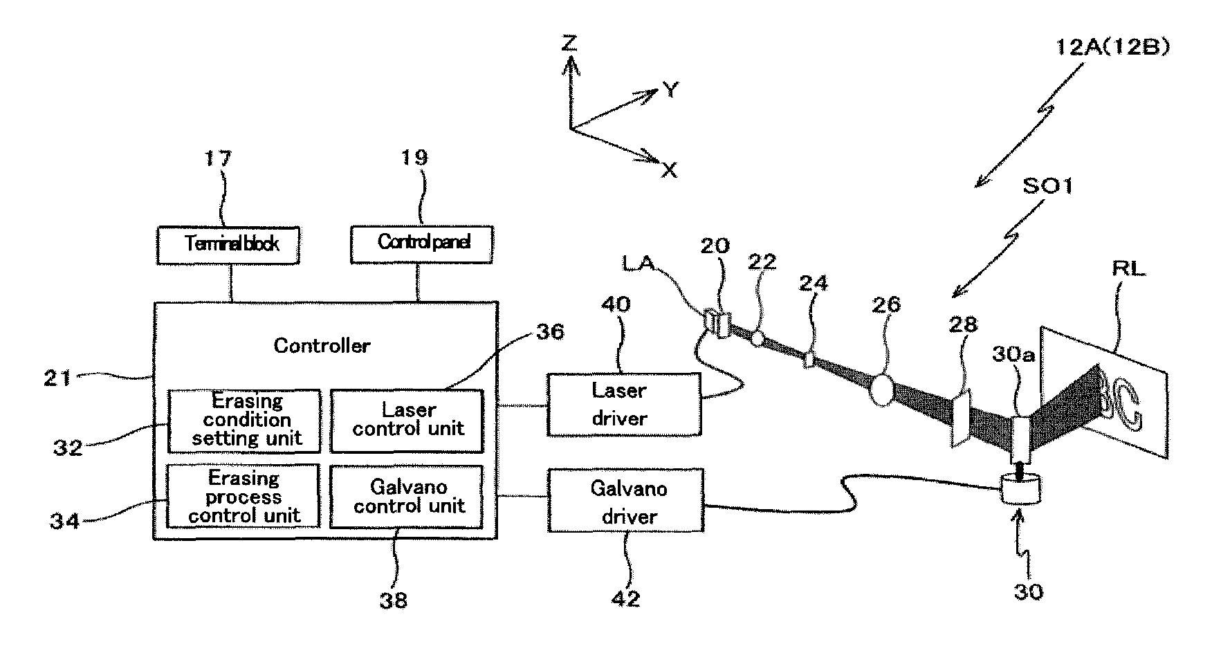
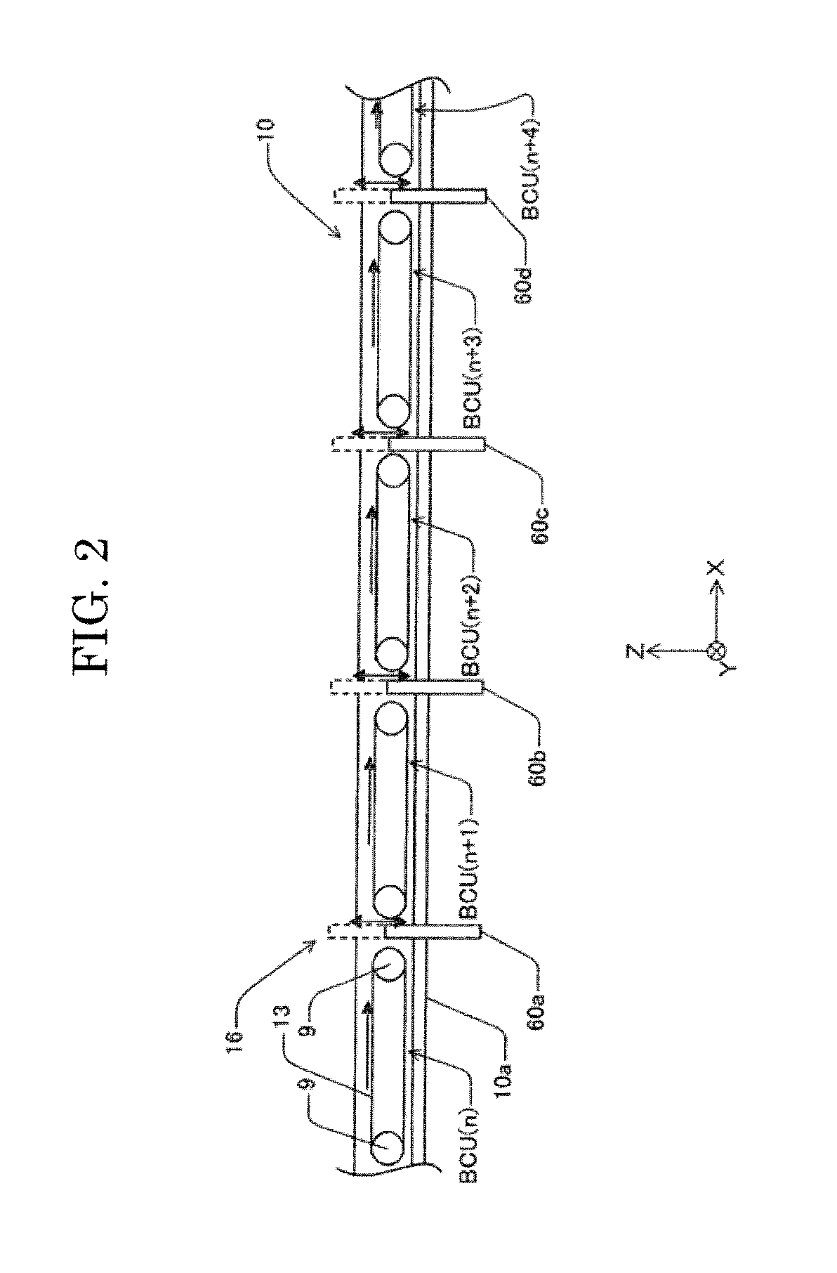
Provided is an image recording system for recording an image on a recording medium attached to a conveyed article, including: a conveyor device conveying the conveyed article in a predetermined conveying direction; and a recording device provided on at least one side of the conveyor device in a direction perpendicular to the conveying direction and capable of contactlessly recording the image on the recording medium being located at a position facing itself. The image includes a scan image to be read by a reading device. The conveyor device decelerates the conveyed article by observing a position at which the recording medium will face the recording device as a target stop position. The recording device records the scan image on the recording medium after the conveyed article reaches the target stop position and while the amplitude of vibration of the conveyed article is equal to or smaller than a reference value.

Description

BACKGROUND OF THE INVENTION[0001]1. Field of the Invention[0002]The present invention relates to an image recording system, an image rewriting system, and an image recording method, and particularly to an image recording system configured to record an image on a recording medium attached to an article being conveyed, an image rewriting system including the image recording system, and an image recording method for recording the image.[0003]2. Description of the Related Art[0004]Conventionally, a technique is known which decelerates a conveyed article, which is being conveyed with a recording medium attached thereon, so that the article may be stopped at a target stop position, which is a predetermined position on the conveying path, and records an image including a scan image (e.g., a barcode) on the recording medium when the conveyed article arrives at the target stop position (e.g., see Japanese Patent Application Laid-Open (JP-A) No. 2008-194905).[0005]However, with the technique ...

Claims


Application Information

Patent Timeline
Patent Type & Authority Patents(United States)
IPC IPC(8): B41J2/435B41J11/00G06K1/12
CPCB41J11/007G06K1/12
Inventor ISHIKAKE, SATORUYAMAMOTO, KAZUTAKA
Owner RICOH KK
Learn More