
Method and device for electrostatically separating overspray with an absorption agent

an absorption agent and electrostatic separation technology, applied in magnetic separation, coatings, chemistry apparatuses and processes, etc., can solve the problems of high energy consumption for air treatment, complex structural measures, and high cost of rinsing water, and achieve advantageous absorption

Active Publication Date: 2015-07-28
EISENMANN AG
View PDF15 Cites 3 Cited by
  • Summary
  • Abstract
  • Description
  • Claims
  • Application Information

AI Technical Summary

Benefits of technology

The invention relates to a method using a wax-like material to prevent overspray from contacting a separating surface. The separating agent can be easily removed from the surface by stripping or shaving it off. This allows the overspray to be disposed of or treated as needed. The use of a plate-shaped separating element with large separating surfaces provides efficiency and ease of handling.

Problems solved by technology

Treating the rinsing water is costly due to the elevated use of paint-binding and detackifying chemicals and the disposal of paint sludge.
Furthermore, as a result of the intensive contact with the rinsing water, the air absorbs a great deal of moisture which, in recirculating-air mode, in turn leads to a high energy consumption for treating the air.
However, for continuous operation, it is necessary to always ensure that a sufficiently strong electrical field can build up between the separating surface and the electrode device, which is only possible up to a certain layer thickness of paint overspray on the separating surface, since such a layer has an insulating effect.
However, the necessary continuous removal of the paint overspray from the separating surface involves complex structural measures and can be prone to faults.
It is moreover possible that overspray will react, harden or dry on the separating surface so that it can no longer be simply removed by being stripped off the separating surface.

Method used


Image

  • Method and device for electrostatically separating overspray with an absorption agent
  • Method and device for electrostatically separating overspray with an absorption agent
  • Method and device for electrostatically separating overspray with an absorption agent

Examples


Embodiment Construction

[0057]While this invention is susceptible of embodiment in many different forms, there is shown in the drawings and will herein be described in detail one or more embodiments with the understanding that the present disclosure is to be considered as an exemplification of the principles of the invention and is not intended to limit the invention to the embodiments illustrated.

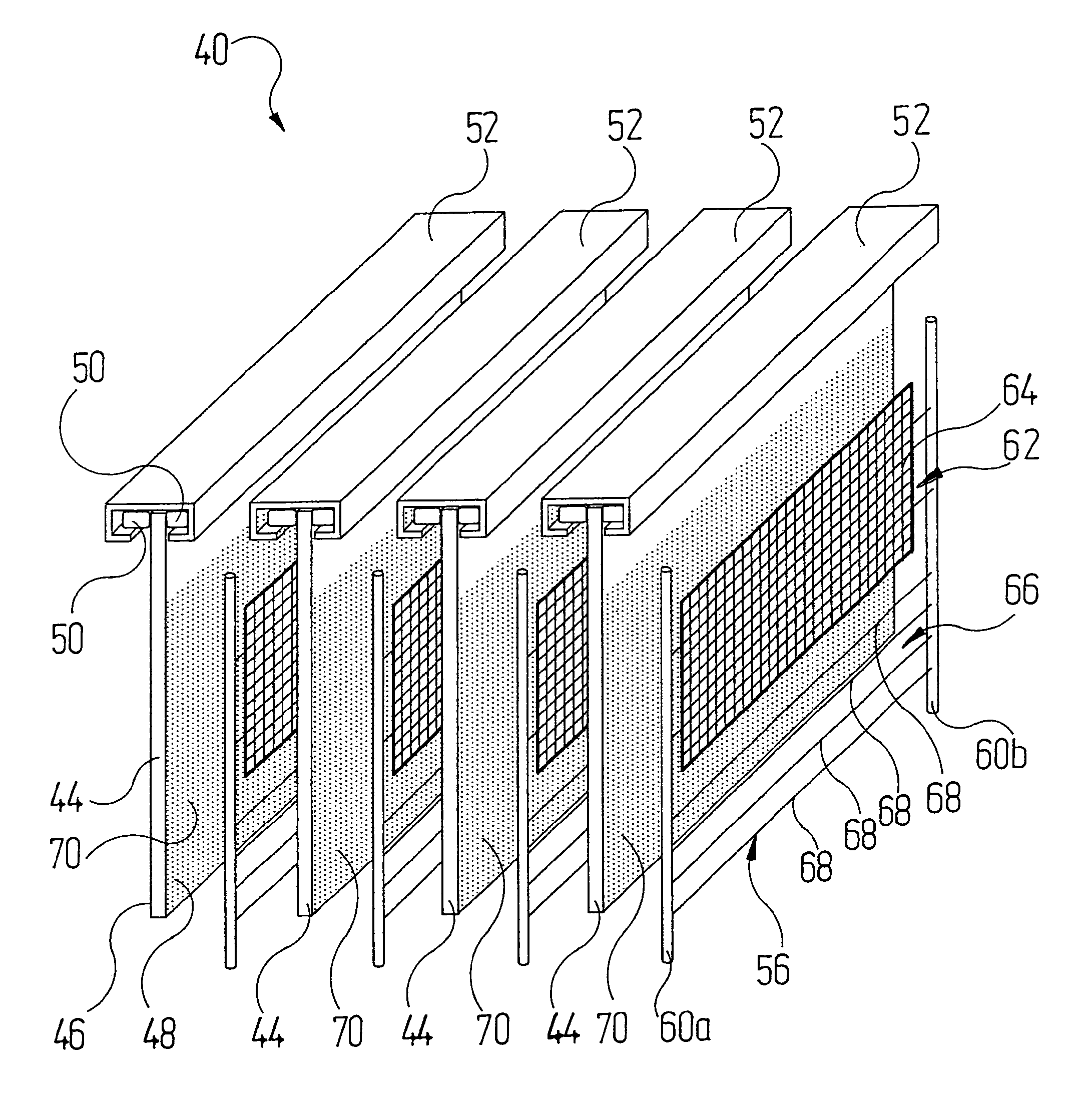
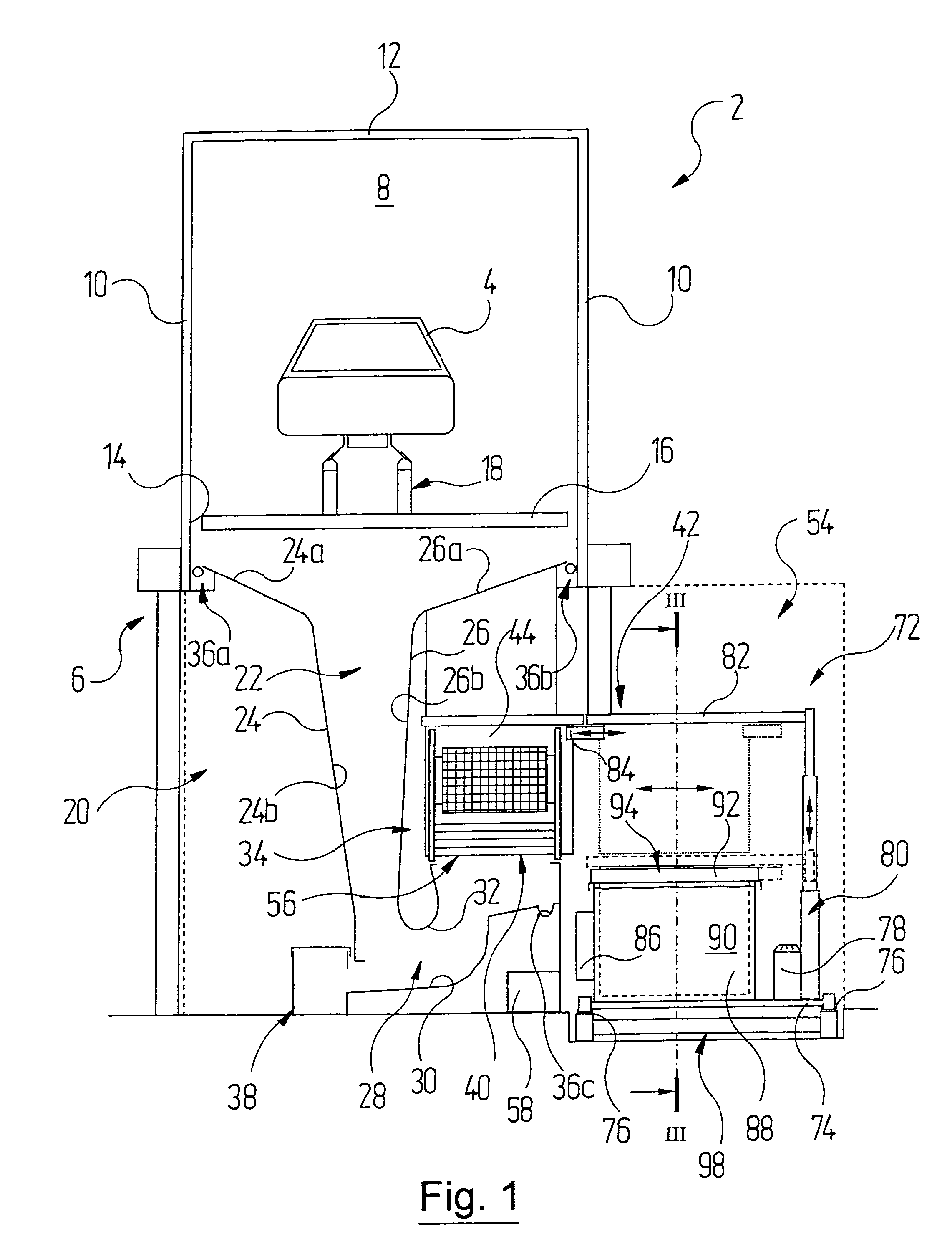
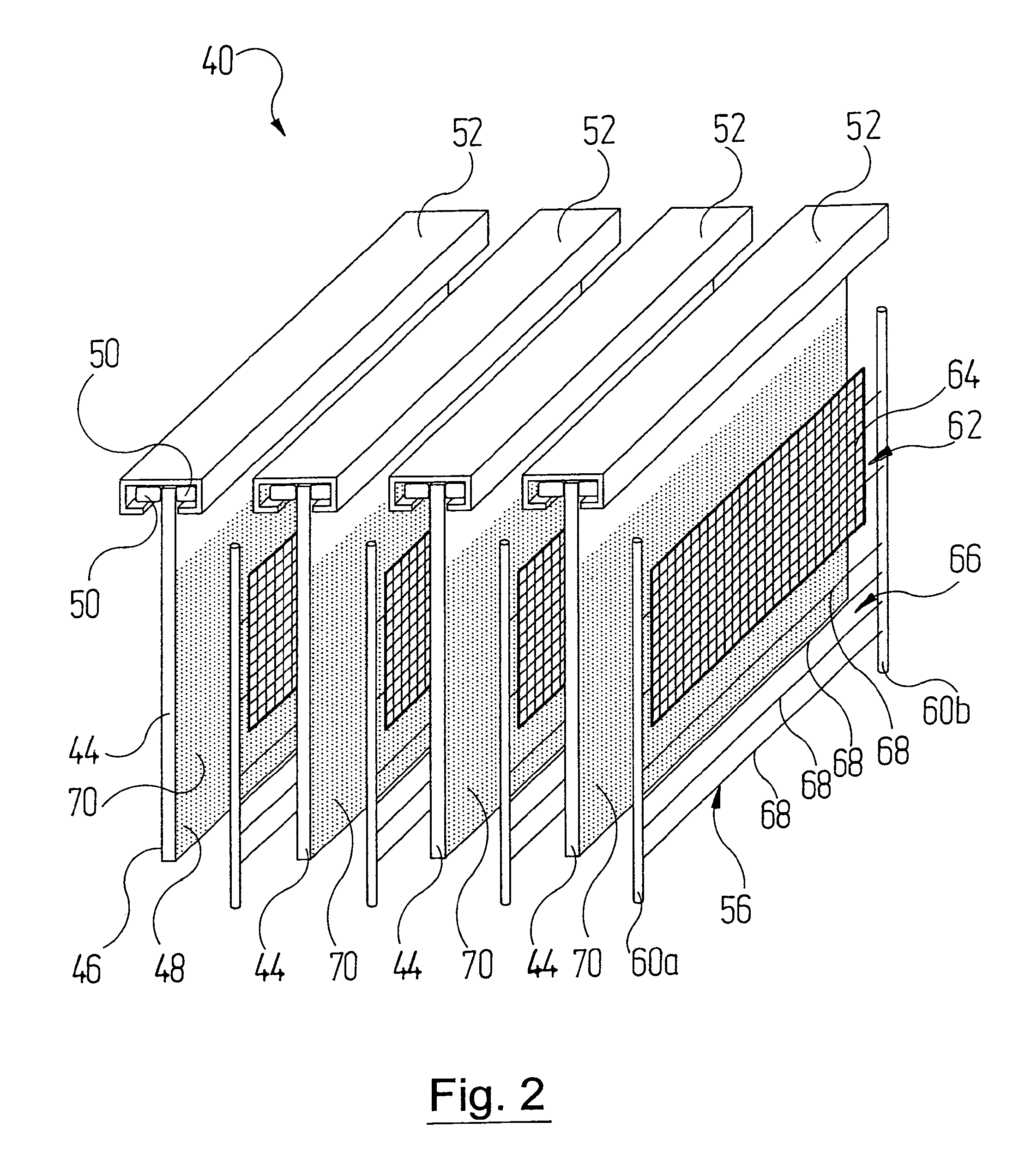
[0058]Reference is firstly made to FIGS. 1 to 3. In these, 2 denotes a paint booth, as a whole, of a surface treatment system in which vehicle bodies 4 are painted after they have been cleaned and degreased, for example, in pre-treatment stations (not shown specifically) arranged upstream in the paint booth 2. The paint booth 2 rests on a steel structure 6 as is known per se.

[0059]The paint booth 2 comprises a paint tunnel 8, which is arranged at the top and is delimited by vertical side walls 10 and a horizontal booth ceiling 12, but is open at the end faces and towards the bottom such that overspray-laden booth...


PUM


Abstract

A method for separating overspray from the cabin exhaust air of coating systems, in particular of painting systems, which is laden with overspray, the overspray is taken up by an air flow and conveyed to an electrostatically operating separating device. There, the bulk at least of the solids is separated from the overspray at at least one separating surface. An electrically conductive material or material mixture is used as a separating agent, which is applied to the at least one separating surface of the separating device and at the operating temperature of the separating device has a wax-like consistency. Also a separating device with such a wax-like material and a system for coating articles.

Description

RELATED APPLICATIONS[0001]This application claims the filing benefit of International Patent Application No. PCT / EP2010 / 007120, filed Nov. 24, 2010, which claims the filing benefit of German Patent Application No. 10 2009 058 206.1 filed Dec. 15, 2009, the contents of both of which are incorporated herein by reference.TECHNICAL FIELD AND BACKGROUND OF THE INVENTION[0002]The invention relates to a method for separating overspray from the overspray-laden booth exhaust air of coating systems, particularly painting systems, in which the overspray is taken up by an air stream and conveyed to an electrostatically operating separating device where the bulk at least of the solids is separated from the overspray on at least one separating surface.[0003]The invention moreover relates to a device for separating overspray from the overspray-laden booth exhaust air of paint systems having[0004]a) at least one separating surface along which the booth exhaust air can be conveyed and which is conne...

Claims


Application Information

Patent Timeline
IPC IPC(8): B03C3/14B03C3/013B05B15/12B03C3/34B03C3/017B03C3/53B05B14/42
CPCB05B15/1244B03C3/013B03C3/017B03C3/53B03C2201/28B05B15/1262B05B14/42B05B14/46
Inventor LINK, KERSTENSWOBODA, WERNERHIHN, ERWINHANF, JUERGEN
Owner EISENMANN AG
Learn More