Drive apparatus for driving a worm of an injection molding machine

a technology of injection molding machine and drive apparatus, which is applied in the direction of friction gearing, belt/chain/gearing, friction gearing, etc., can solve the problems of wear and undesired rotational play between the two drives, and achieve the effect of reducing the risk of failure and increasing the rigidity of the driv

Active Publication Date: 2015-07-14
WITTENSTEIN SE
View PDF9 Cites 4 Cited by
  • Summary
  • Abstract
  • Description
  • Claims
  • Application Information

AI Technical Summary

Benefits of technology

[0011]Typical drive apparatuses of the invention comprise a translatory drive with a spindle rotor which interacts with a spindle shaft. The spindle shaft is preferably arranged at least partially coaxially within the spindle rotor. In embodiments, the spindle shaft is fixed completely. This means, in particular, that the spindle shaft is immovable. In typical embodiments, the housing can therefore be displaced relative to the spindle shaft. In further embodiments, the spindle shaft can also rotate. A fixed spindle shaft affords a reliable abutment which can be of particularly rigid configuration. In typical embodiments of drive apparatuses, the spindle shaft is mounted in a rotationally fixed and axially non-displaceable manner, in particular in a rotationally fixed and axially non-displaceable manner with respect to a housing of an injection molding machine. A reliable abutment is produced as a result.
[0013]The rotational drive of typical embodiments comprises a rotor which is coupled to the output shaft in a fixed manner. A direct transmission of force is achieved in this way. The rotor is typically mounted rotatably with respect to the housing. Rotors of embodiments which are mounted non-displaceably with respect to the housing afford the possibility of an attachment of the output shaft to the housing, which attachment is non-displaceable in the axial direction and is therefore rigid.
[0015]The spindle rotor is typically mounted rotatably at a first axial end partially within the rotor. An intermediate bearing or radial / axial bearing is typically arranged between the spindle rotor and the rotor, in order to mount the spindle rotor on both sides, but to decouple a rotation between the spindle rotor and the rotor. The spindle rotor is typically mounted at its second axial end in the housing. Reliable support is produced in this way and the force flow advantageously runs within the rotating components. This increases the rigidity in the drive and minimizes the risk of failure, since critical components and interfaces, such as the housing or the adhesive bond between stators and housing, are virtually load-free.

Problems solved by technology

In the devices from the prior art, a long overall design, a coupling which is subject to wear and a possible rotational play between the two drives can be undesired.

Method used


Image

  • Drive apparatus for driving a worm of an injection molding machine
  • Drive apparatus for driving a worm of an injection molding machine
  • Drive apparatus for driving a worm of an injection molding machine

Examples


Embodiment Construction

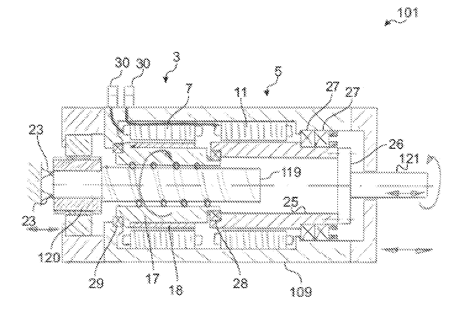
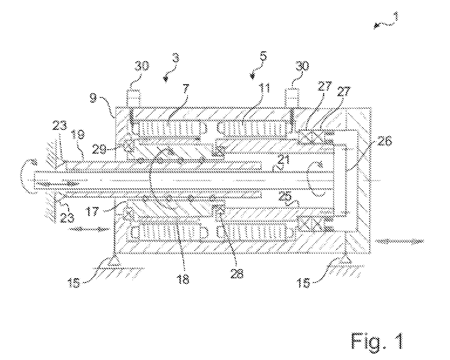
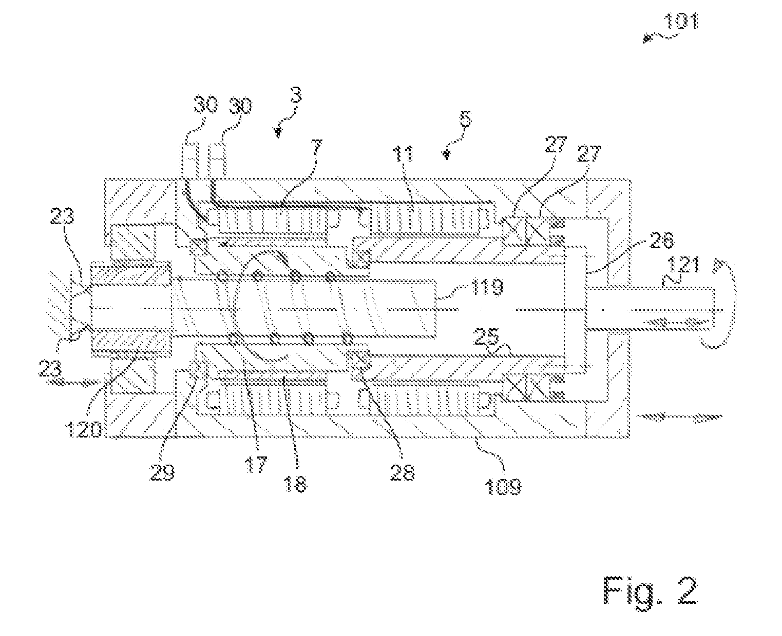
[0019]FIG. 1 shows a drive apparatus 1 with a translatory drive 3 and a rotational drive 5. The translatory drive 3 comprises a translatory stator 7 which is connected to a housing 9 of the drive apparatus 1 in a fixed manner. The rotational drive 5 comprises a rotational stator 11 which is likewise arranged in the housing 9 in a fixed manner. The rotational stator 11 and the translatory stator 7 are arranged axially one behind another in the housing 9.

[0020]The housing 9 is mounted by way of two merely diagrammatically shown bearings 15 such that it can be displaced in the axial direction. The bearings can be configured, for example, as displacement sleeves which are mounted on rods. Further possibilities which are utilized by embodiments are bearing slides or linear guides which are guided on rails. The mounting can take place via elements which are mounted by plain bearings and ball bearings or roller bearings. Moreover, the bearings 15 bring about rotationally locked mounting of...


PUM

PropertyMeasurementUnit
degrees of freedomaaaaaaaaaa
rotationaaaaaaaaaa
forceaaaaaaaaaa

Abstract

Drive apparatus (1, 101), in particular for driving a worm of an injection molding machine, which worm is arranged coaxially with respect to an injection molding cylinder, having a housing (9, 109) which is mounted such that it can be displaced in an axial direction of the housing (9, 109) and is fixed rotationally, an output shaft (21, 121) which is mounted non-displaceably and rotatably in the housing (9, 109), a rotational drive (5) which is arranged in the housing (9, 109) for the rotational drive of the output shaft (21, 121), and a translatory drive (3) which is arranged in the housing (9, 109) for the translatory drive of the housing (9, 109).

Description

BACKGROUND OF THE INVENTION[0001]The invention relates to a drive apparatus and to the use of a drive apparatus for driving a worm of an injection molding machine, which worm is arranged coaxially with respect to an injection molding cylinder.[0002]Drive systems for driving a worm of an injection molding machine, which worm is arranged coaxially with respect to an injection molding cylinder, are known from the prior art. In combined drive systems which consist of a rotating and a linear drive, the two drives are designed in each case as an independent system and are connected by means of a coupling system.[0003]DE 103 04 578 B3 discloses an injection assembly having two motors for the separate driving of two degrees of freedom of a worm. Here, a first motor drives a spindle, on which a spindle nut is arranged. The spindle nut is connected to a second motor which can be displaced together with the spindle nut. The second motor serves to bring about a rotation of the worm.[0004]In the...

Claims


Application Information

Patent Timeline
Patent Type & Authority Patents(United States)
IPC IPC(8): B29C45/50F16H19/02B29C45/76
CPCF16H19/02B29C45/5008B29C45/76B29C2045/5024Y10T74/18792F16H25/2018B29C2045/504F16H2025/2075
Inventor SCHWARZBACH, MICHAELUHL, DIETER
Owner WITTENSTEIN SE
Why Eureka
Try Eureka