Solar cell module and manufacturing method thereof

a solar cell and module technology, applied in the field of solar cell modules, can solve the problems of reducing the possibility of the thermal radiation material layer being peeled off from the solar cell device, and achieve the effect of improving power generation efficiency

Inactive Publication Date: 2015-07-07
WIN WIN PRECISION TECH
View PDF7 Cites 0 Cited by
  • Summary
  • Abstract
  • Description
  • Claims
  • Application Information

AI Technical Summary

Benefits of technology

[0008]It is therefore an objective of the present invention to provide a solar cell module of better power generation efficiency.
[0019]Thus, the solar cell module herein is equipped with the thermal radiation material layer sandwiched between the solar cell device and the backplane to effectively dissipate heat out of the module by maximizing its thermal radiation rate. Therefore, a power generation efficiency of the solar cell module can be enhanced due to a lower operation temperature. In addition, the thermal radiation material layer is partially covered over the electrode layer to at least expose the metal electrodes so as to reduce the broken piece and enhance the yield of the solar cell module. The thermal radiation material layer is formed by screen printing, which makes the thermal radiation material layer firmly attached to the solar cell device, thereby reducing the possibility of the thermal radiation material layer being peeled off from the solar cell device.

Problems solved by technology

In the case of petrochemical energy shortages as well as the increasing demand for energy, the development of renewable energy become one of the very important issues.
The thermal radiation material layer is formed by screen printing, which makes the thermal radiation material layer firmly attached to the solar cell device, thereby reducing the possibility of the thermal radiation material layer being peeled off from the solar cell device.

Method used


Image

  • Solar cell module and manufacturing method thereof
  • Solar cell module and manufacturing method thereof
  • Solar cell module and manufacturing method thereof

Examples


Embodiment Construction

[0026]Reference will now be made in detail to the present preferred embodiments of the invention, examples of which are illustrated in the accompanying drawings. Wherever possible, the same reference numbers are used in the drawings and the description to refer to the same or like parts.

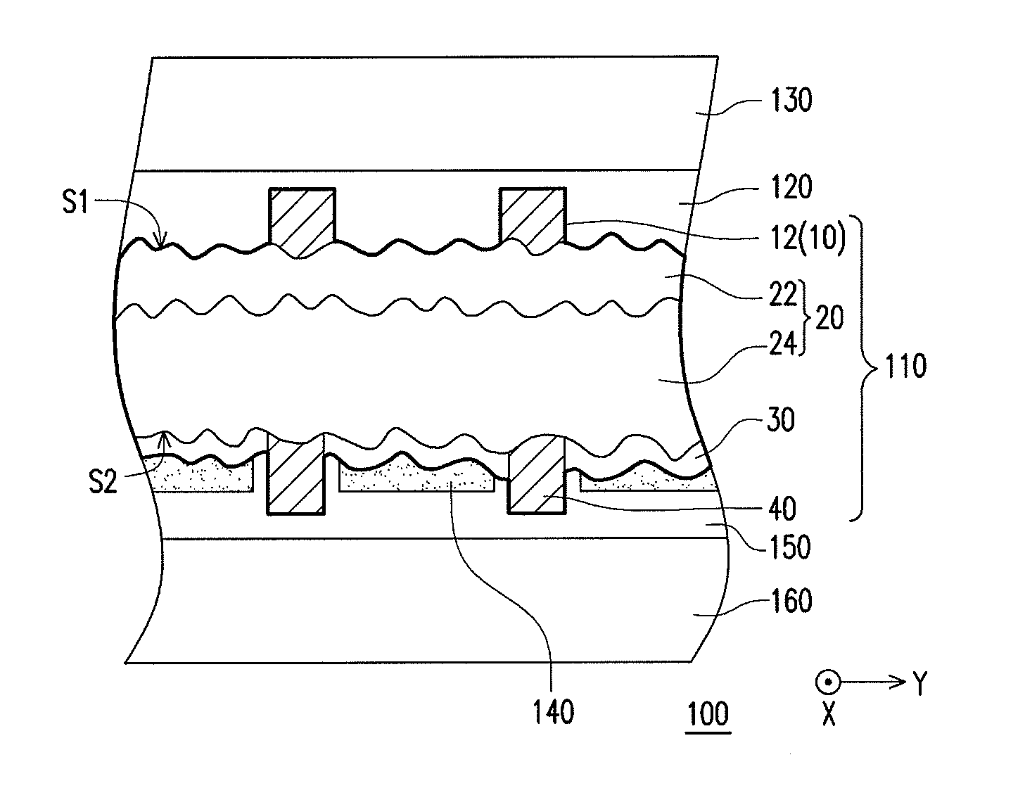
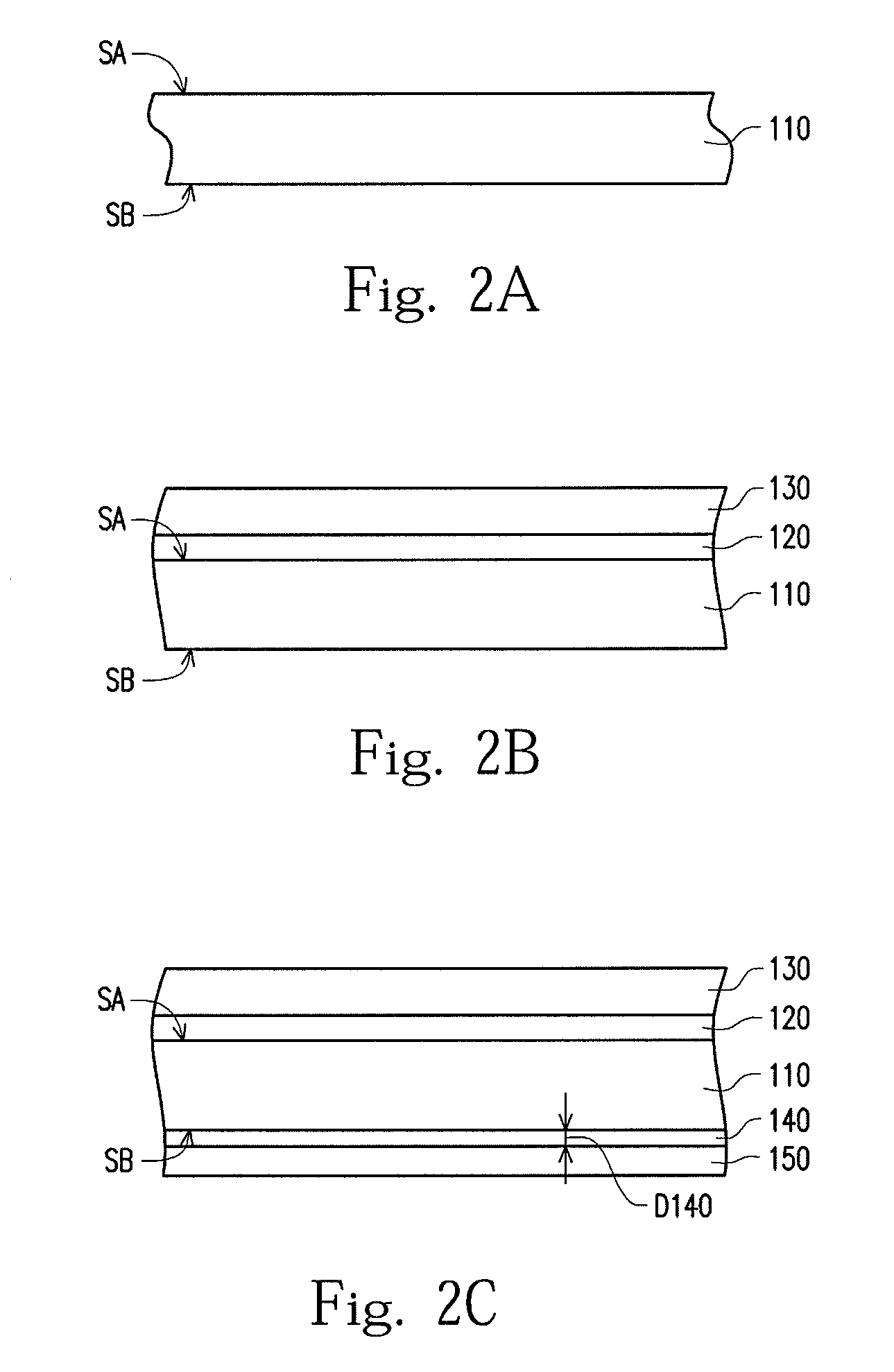
[0027]FIG. 1 illustrates a flowchart for manufacturing a solar cell module according to one preferred embodiment of this invention. In step S100, a solar cell device, which includes a light-receiving surface and a non-light-receiving surface opposite to the light-receiving surface, is provided. Then, in step S200, a first protective film and a cover plate are formed on the light-receiving surface of the solar cell device. The first protective film is located between the solar cell device and the cover plate. In step S300, a thermal radiation material layer is screen printed and a second protective film is formed on the non-light-receiving surface of the solar cell device. Finally, in step S400, a bac...


PUM


Abstract

A solar cell module and a manufacturing method thereof are provided. A solar cell device including a light receiving surface and a non-light-receiving surface opposite to the light-receiving surface is provided. A first protective film and a cover plate are formed on the light-receiving surface, wherein the first protective film is located between the solar cell device and the cover plate. A thermal radiation material layer is screen printed and a second protective is formed on the non-light-receiving surface. A backplane is formed on the non-light-receiving surface, wherein the second protective film is located between the solar cell device and the backplane.

Description

RELATED APPLICATIONS[0001]This application claims priority to Taiwanese Application Serial Number 101135571, filed Sep. 27, 2012, which is herein incorporated by reference.BACKGROUND[0002]1. Field of Invention[0003]The present invention relates to a solar cell module and a manufacturing method thereof.[0004]2. Description of Related Art[0005]In the case of petrochemical energy shortages as well as the increasing demand for energy, the development of renewable energy become one of the very important issues. Renewable energy refers to natural sustainable and non-polluting energy sources, such as solar energy, wind energy, water energy, tidal energy or biomass energy. Solar energy research and development in recent years is also important and popular.[0006]The solar cell is a photovoltaic device, which converts light energy into electricity. The solar cells include single-crystal silicon, polycrystalline silicon, amorphous silicon, thin-film and dye solar cells. Single-crystal silicon ...

Claims


Application Information

Patent Timeline
Patent Type & Authority Patents(United States)
IPC IPC(8): H01L31/052H01L31/0216H01L31/048
CPCH01L31/052H01L31/048H01L31/02167Y02E10/50H02S40/42
Inventor WANG, CHENG-LIEN
Owner WIN WIN PRECISION TECH
Why Eureka
Try Eureka