
Method for production of a three-dimensional body

a three-dimensional body and body technology, applied in the direction of electric/magnetic/electromagnetic heating, additive manufacturing processes, instruments, etc., can solve the problems of difficult real-time correction or control of beams based on input from such cameras, difficult to perform properly, and the need for more complex scan patterns, etc., to achieve the effect of simplifying and speeding up the calculation, and reducing the production tim

Active Publication Date: 2015-07-07
ARCAM AB
View PDF95 Cites 124 Cited by
  • Summary
  • Abstract
  • Description
  • Claims
  • Application Information

AI Technical Summary

Benefits of technology

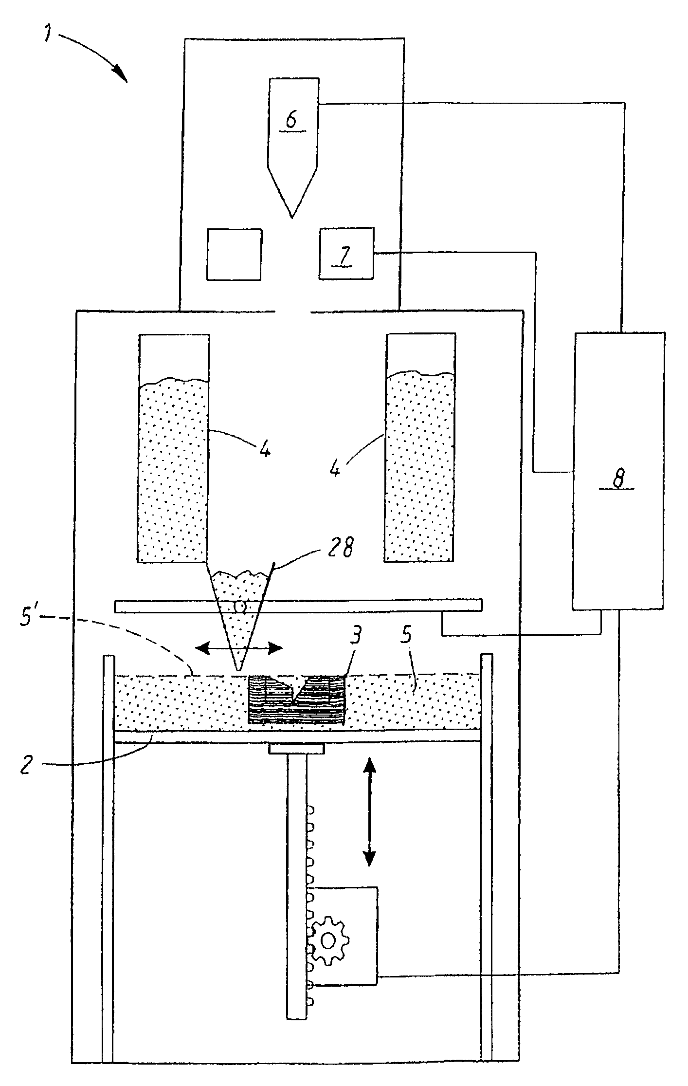
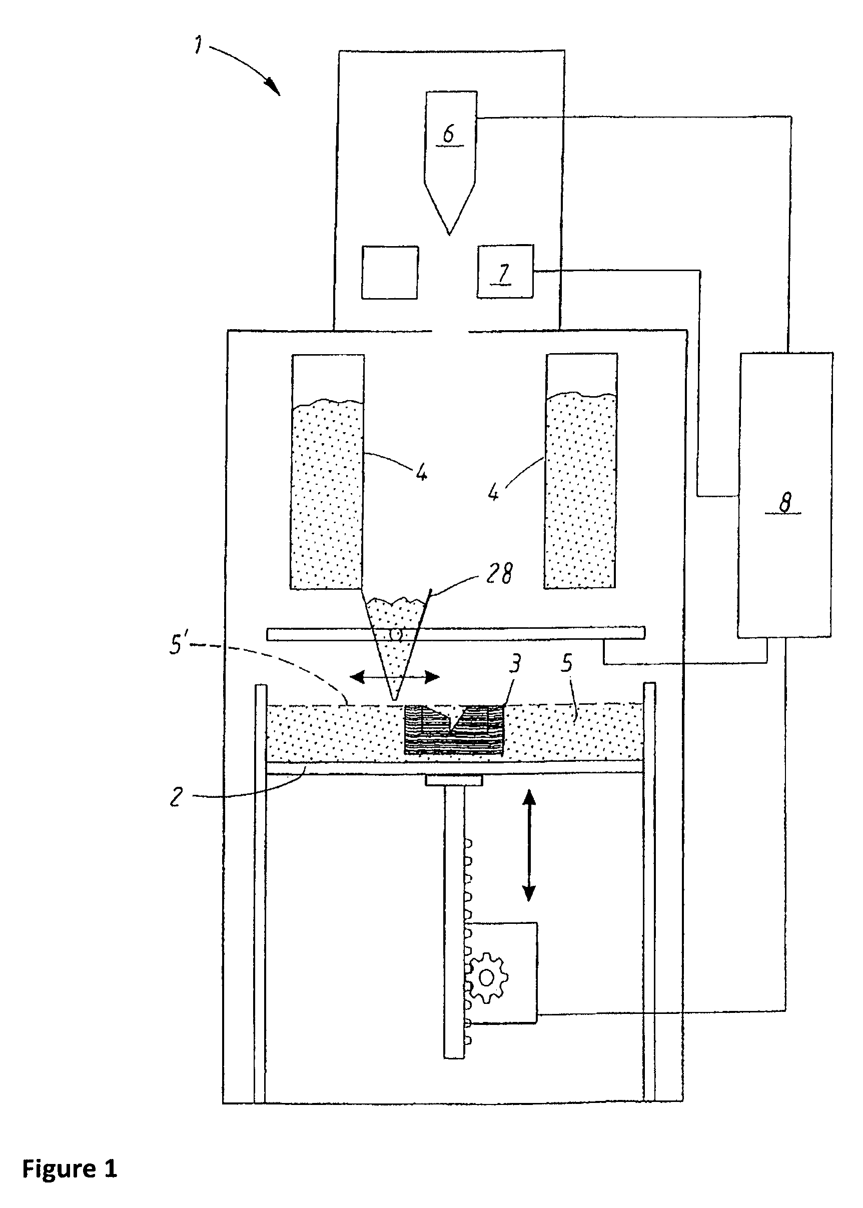
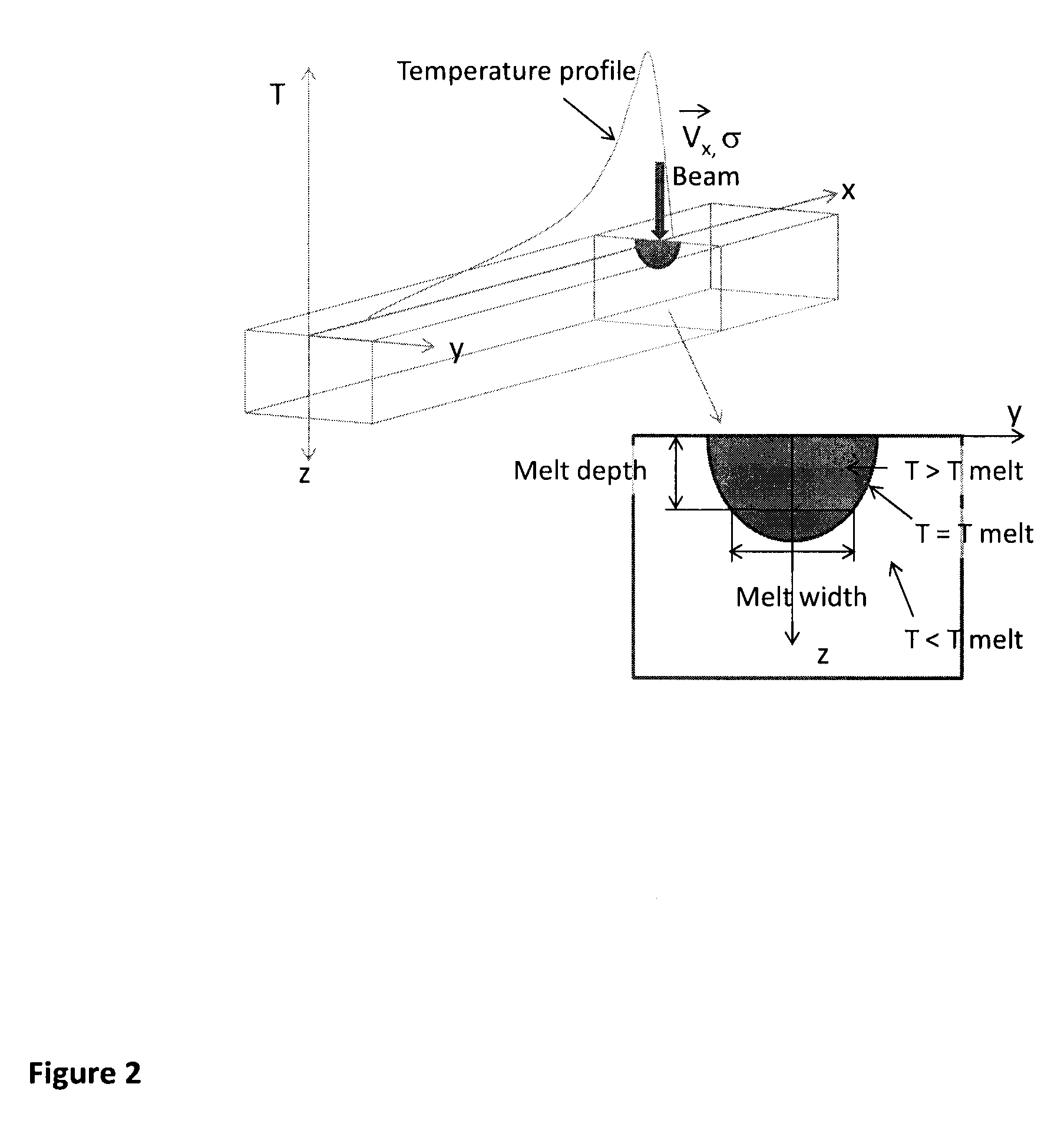
The present invention provides a method for adjusting the specific energy deposition of a beam used for fusing powder in a 3D printing process. By calculating the temperature along the beam path for different specific energy depositions and conditions, the method makes it possible to pre-adjust the specific energy deposition of the beam to vary in response to the temperature buildup for the particular scan pattern being used. This allows for precise control over the temperature and temperature distribution in the selected area, and thus can improve the quality and speed of the 3D printing process. The method can also make the production process more cost-effective by avoiding excessive temperatures and reducing stress and crack formation.

Problems solved by technology

For instance, a too high local temperature might destroy the object being produced and a too inhomogeneous temperature distribution might lead to cracks.
Real-time corrections or controlling of the beam based on input from such a camera is, however, difficult to perform properly because of the long response time of the system (even if actions are taken to decrease the temperature immediately when an increased temperature has been detected the temperature is likely to continue increasing for some time).
Moreover, if the beam energy is high a more complex scan pattern may be required.
In such cases the temperature build-up will not be properly taken into account just by varying the beam speed with respect to the length of the scan lines.
However, this would lead to a rather time-consuming production process.

Method used


Image

  • Method for production of a three-dimensional body
  • Method for production of a three-dimensional body
  • Method for production of a three-dimensional body

Examples


example

[0126]In the following hatch example (cf. FIG. 7) a trapezoid will be melted with a constant beam power and it will be the beam speed that is varied in order to have constant melt depth and melt width. The intended beam path is such that the beam starts to scan the lines in FIG. 7 from the bottom to the top by altering the direction from left to right to right to left.

[0127]The spot size has been optimized for Tsurf, the temperature in the part prior to fusing, such that the maximum temperature in the melt pool is limited to Tmax. This means that the first hatch line is scanned with a constant speed and a fixed spot size. All the other lines are scanned with the same spot size and power but with different and varying speeds. The speed in each point of calculation distributed along the intended beam path is obtained by first calculating the temperature distribution around the point and then from speed versus temperature data in the data base. The speed in the data base has been optim...


PUM

PropertyMeasurementUnit
temperatureaaaaaaaaaa
areasaaaaaaaaaa
energyaaaaaaaaaa

Abstract

The invention concerns a method for production of a three-dimensional body by successively providing powder layers and fusing together of selected areas of said layers, which areas correspond to successive cross sections of the three-dimensional body, wherein the method comprises the following steps for at least one of said layers: applying the at least one powder layer onto a working area, and fusing together a selected area of the at least one powder layer by supplying energy from a radiation gun to the selected area. The invention is characterized in that it comprises the steps of: establishing an intended beam path that is to be used when fusing together the selected area of the at least one powder layer, calculating a temperature in the at least one powder layer along the intended beam path as a function of a specific energy deposition of an imaginary beam that is assumed to move along the intended beam path, adjusting the specific energy deposition of the imaginary beam along the intended beam path depending on the calculated temperature and on conditions set for the step of fusing together the selected area, and providing, based on the calculations and the adjustments, an operating scheme for the specific energy deposition of the real beam to be used for the intended beam path when fusing together the selected area of the at least one layer.

Description

CROSS REFERENCE TO RELATED APPLICATIONS[0001]This application is a national stage application, filed under 35 U.S.C. §371, of International Application No. PCT / SE2011 / 050093, filed Jan. 28, 2011, the content of which is hereby incorporated by reference in its entirety.BACKGROUND[0002]1. Related Field[0003]This invention relates to a method for production of a three-dimensional body by successively providing powder layers and fusing together of selected areas of said layers, which areas correspond to successive cross sections of the three-dimensional body.[0004]2. Description of Related Art[0005]Equipment for producing a three-dimensional object layer by layer using a powdery material which can be fused together and solidified by irradiating it with a high-energy beam of electromagnetic radiation or electrons are known from e.g. U.S. Pat. No. 4,863,538, U.S. Pat. No. 5,647,931 and SE524467. Such equipment include for instance a supply of powder, means for successively applying layers...

Claims


Application Information

Patent Timeline
Patent Type & Authority Patents(United States)
IPC IPC(8): B29C41/02B29C41/52B22F3/105G06F19/00B29C67/00B29C41/00G05D23/00B29K105/00
CPCB29C67/0077B29C41/003G05D23/00G06F19/00B29C41/52B22F3/1055B29C67/0088B29K2105/251B33Y50/02B29C64/153B29C64/393B33Y10/00Y02P10/25G16Z99/00B22F10/28B22F10/36B22F10/366B22F10/80
Inventor SNIS, ANDERS
Owner ARCAM AB
Learn More