
Optical determination and reporting of hydrocarbon properties

a technology of hydrocarbon properties and optical determination, applied in the field of chemical analysis systems and methods, can solve the problems of unrealized profits from a well or field, unfavorable reporting of hydrocarbon properties, and unrealistic use of only one sample to describe the quality of gas for an entire quarter, etc., and achieve the effect of fair net present value and accurate pricing structur

Active Publication Date: 2015-06-16
JP3 MEASUREMENT
View PDF2 Cites 12 Cited by
  • Summary
  • Abstract
  • Description
  • Claims
  • Application Information

AI Technical Summary

Benefits of technology

This solution enables continuous, accurate determination of natural gas properties, optimizing pricing, equipment configuration, and maintenance scheduling, reducing latency-related issues and equipment damage, and improving operational efficiency by providing real-time data for better decision-making.

Problems solved by technology

However, changes in the gas content, for the better or worse, may result in unrealized profits from a well or field.
In the case of declining quality, penalties may be imposed on the supplier by delivering product from a field that does not meet the previously stated product requirements.
Thus, using only one sample to describe the quality of the gas for an entire quarter is unrealistic.
As not all the wells may be on service at the time of the sample, the removal from service of a high energy well may adversely impact the measured quality.
Additionally, the potentially large latency between samples may result in undetected rising levels of contaminants such as hydrogen sulfide, carbon dioxide, water, nitrogen, and other like contaminates that do not contribute to the energy content of the gas.
This may result in the gases exceeding the specified levels during the periodicity between samples.
This in turn may result in damage to processing or manufacturing equipment and fines for the supplier.

Method used


Image

  • Optical determination and reporting of hydrocarbon properties
  • Optical determination and reporting of hydrocarbon properties
  • Optical determination and reporting of hydrocarbon properties

Examples


Embodiment Construction

[0018]Preferred embodiments of the present invention are illustrated in the FIGUREs, like numerals being used to refer to like and corresponding parts of the various drawings.

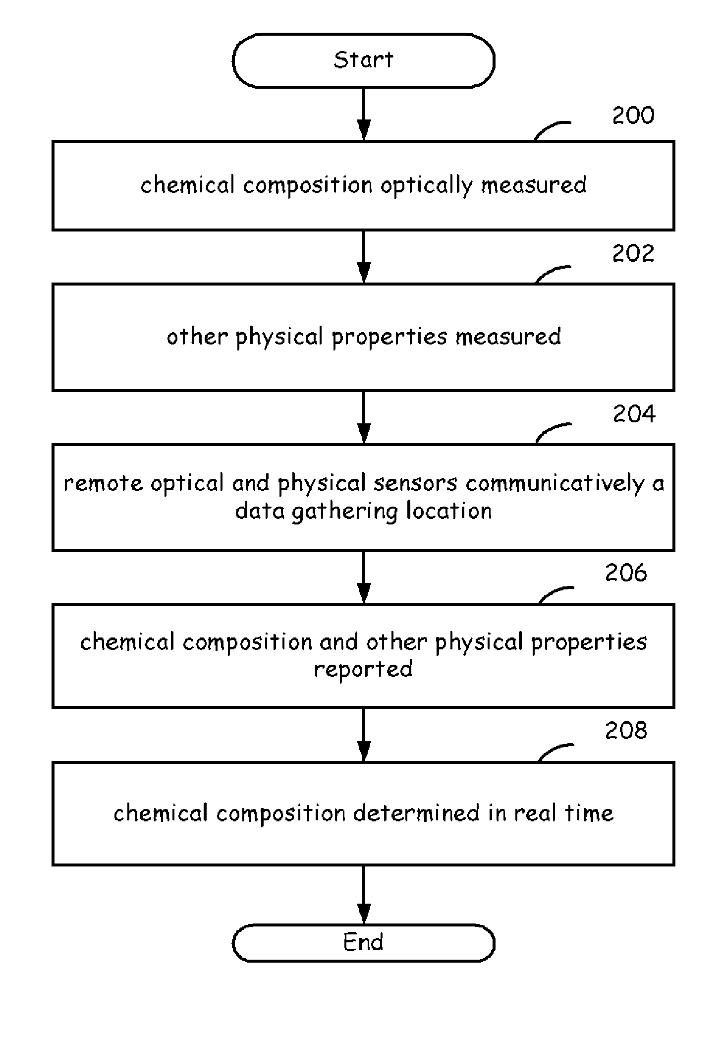
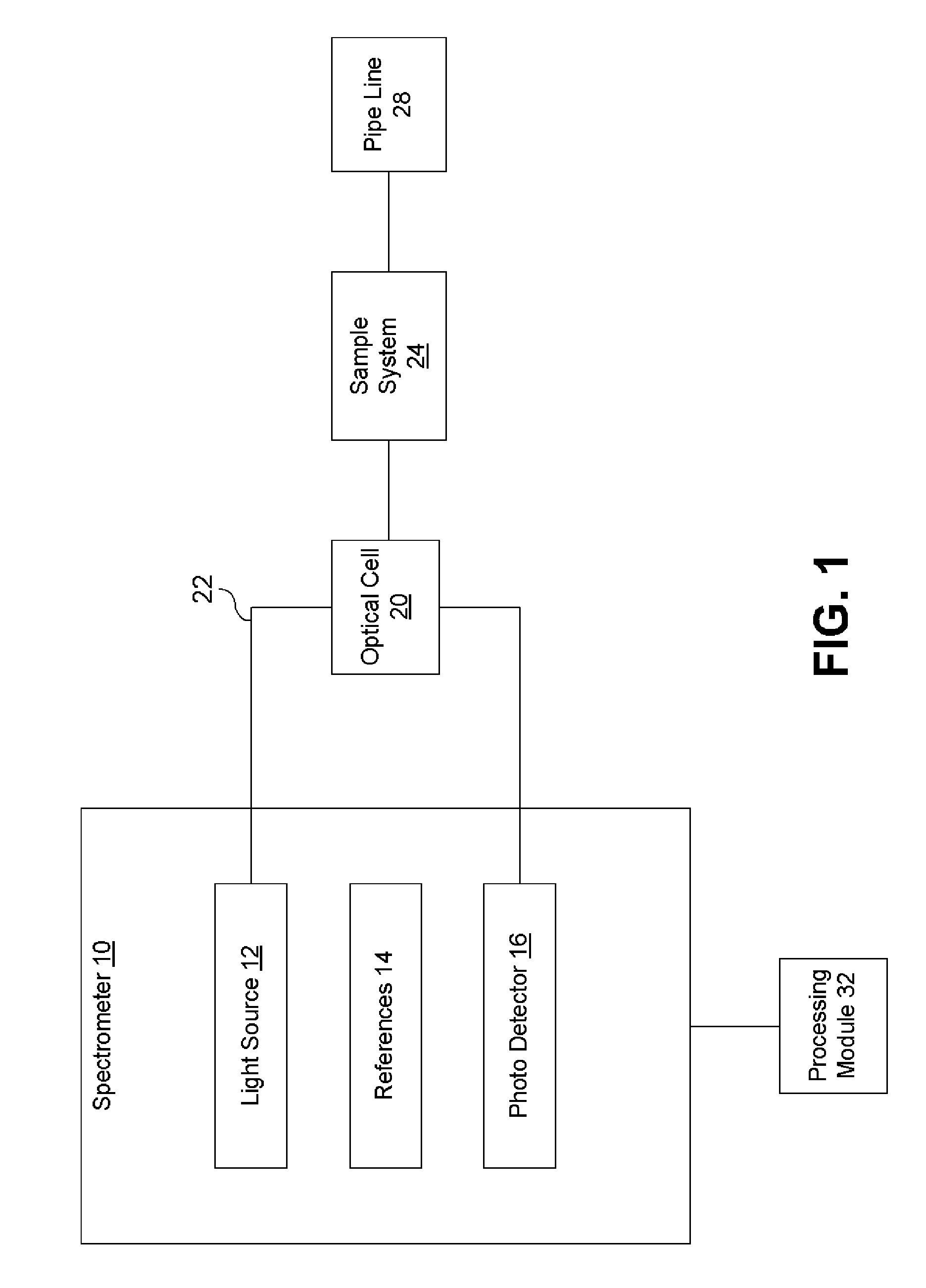
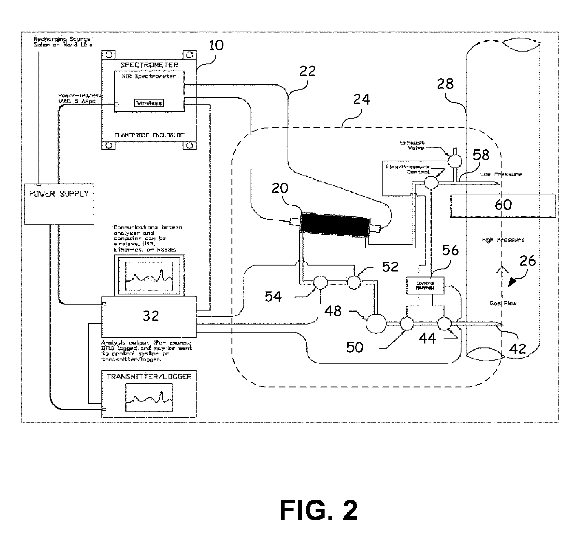
[0019]Embodiments of the present invention provide a way of optically determining the chemical composition of natural gas to derive the energy content (expressed in British Thermal Units (BTU)), hydrocarbon dew point, compressibility, specific gravity, moisture content, impurities, Wobbe index and other like properties associated with hydrocarbons such as but not limited to natural gas. Embodiments may employ the Near Infrared band of the electromagnetic spectrum, specifically between the 1300 nm to 2500 nm range. We will be focusing on the 1550 nm to 1800 nm range to resolve the chemicals that contribute energy content to natural gas. This is a C—H overtone region of the spectrum.

[0020]Another embodiment of the present invention provides a way of electronically gathering and reporting optically determined chem...


PUM

PropertyMeasurementUnit
pressuresaaaaaaaaaa
chemical compositionaaaaaaaaaa
electromagnetic spectrumaaaaaaaaaa

Abstract

A chemical composition analyzer may be used to optically determine and report chemical compositions associated with natural gases within a gas collection and transmission infrastructure. This analyzer includes a number of optical sensors which may be used to perform spectroscopic spectrographic analysis in order to determine the chemical composition of the natural gas. Additionally other sensors may be used to measure other physical properties associated with the natural gas. These sensors are tied to a data collection system wherein the output of the optical sensors and sensors used to measure the physical properties of the natural gas may be combined and processed in order to determine in a nearly continuous fashion the chemical composition associated with the natural gas at various locations within the gas collection and transmission infrastructure. This real time compositional analysis may be used to determine valuations of the gas or to optimize other processes or equipment configurations.

Description

RELATED APPLICATIONS[0001]This application claims priority under 35 USC §119 (e) to and incorporates by reference for all purposes the provisionally filed patent application entitled “Spectrographic Analysis of Hydrocarbons,” Ser. No. 60 / 724,025 filed on Oct. 6, 2005 to inventor Paul Little and provisionally filed patent application entitled “Communication and Reporting of Optically Measured Properties of Hydrocarbons,” Ser. No. 60 / 761,981 filed on Jan. 25, 2006 to inventor Paul Little.TECHNICAL FIELD OF THE INVENTION[0002]The present invention relates generally to chemical analysis systems and methods, and more particularly, a system and method to optically determine chemical properties of a gas.BACKGROUND OF THE INVENTION[0003]Current practices use gas chromatography (GC) to periodically sample natural gas to determine the chemical composition within a gas collection and transmission facility. For example, gas chromatography is often performed on a monthly or quarterly basis to de...

Claims


Application Information

Patent Timeline
Patent Type & Authority Patents(United States)
IPC IPC(8): G01N33/00G01N33/24G01N21/3504G01N21/359G01N21/00G06F17/00
CPCG01N33/241G01N21/359G01N21/3504Y10T436/21
Inventor LITTLE, III, JOSEPH PAUL
Owner JP3 MEASUREMENT
Learn More