
Shielding wall for a fuel supply duct in a turbine engine

a turbine engine and fuel supply duct technology, which is applied in the direction of burners, hot gas positive displacement engine plants, combustion processes, etc., can solve the problems of limiting the exchange of heat between fuel and burner hubs, space available in the hub, etc., and achieve the effect of reducing thermally induced stresses in the burner hub

Inactive Publication Date: 2015-06-16
SIEMENS AG
View PDF14 Cites 0 Cited by
  • Summary
  • Abstract
  • Description
  • Claims
  • Application Information

AI Technical Summary

Benefits of technology

[0008]An object of the present invention is to reduce thermally induced stresses in the burner hub of the burner arrangement.
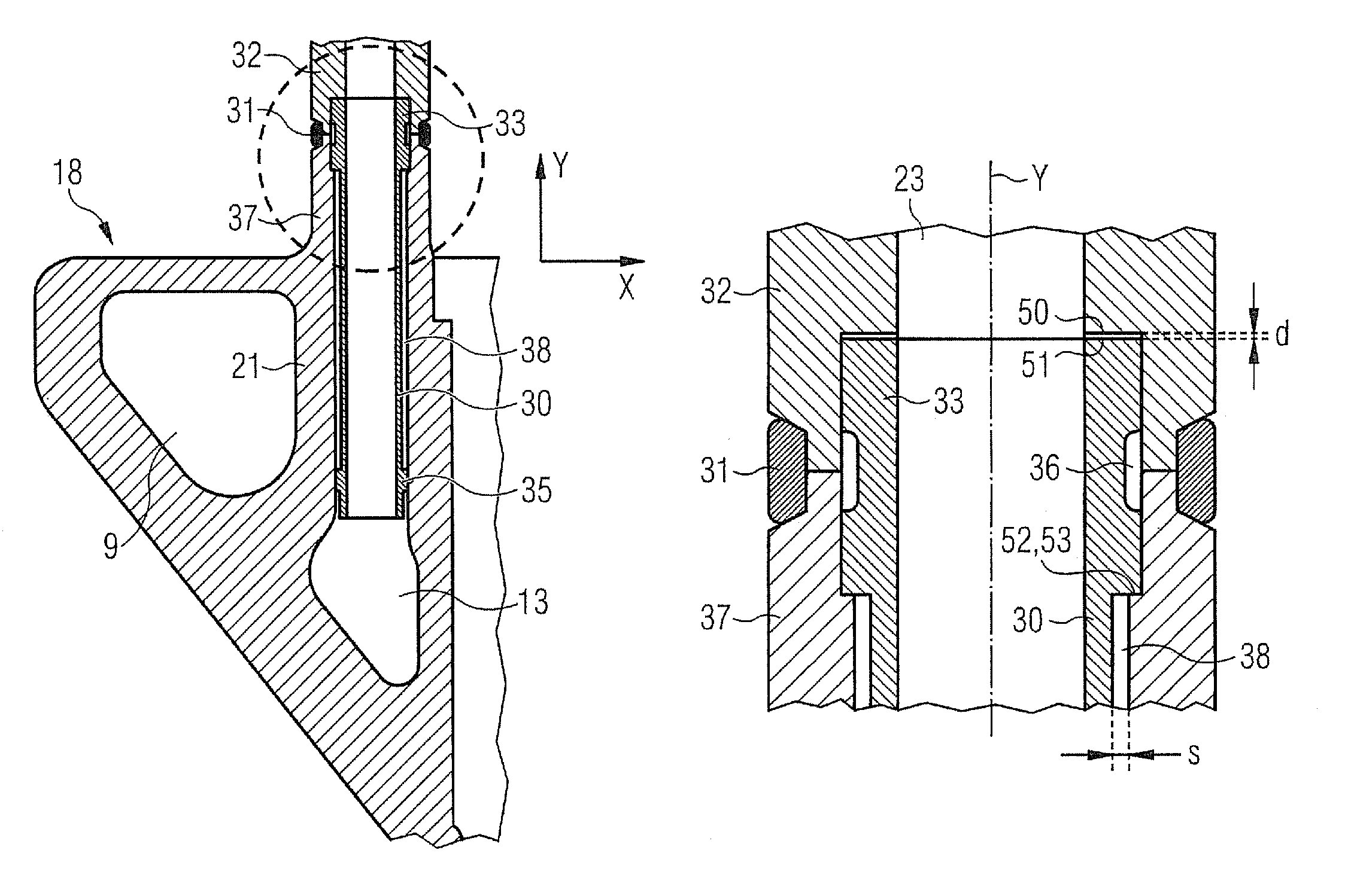
[0011]In the inventive burner arrangement the intermediate space forms a poor heat-conducting region compared with the surrounding metal of the burner hub, thermally insulating the metal of the hub from the flowing fuel and thereby limiting the exchange of heat between the fuel and the burner hub. In particular the sleeve can feature at least one positioning projection respectively running in a circle in the region of its two ends. This makes the alignment of the sleeve apparatus more reliable and the natural vibrations that may occur due to the clearance gaps in the fuel flow are excluded.
[0013]The sleeve can also be equipped with at least one axial positioning means, which interacts with at least one axial positioning means present in the fuel supply duct to position the sleeve axially. This allows axial positioning of the sleeve without a material-fit connection. There may in particular be an axial clearance here between the axial positioning means of the sleeve and the axial positioning means in the fuel supply duct, allowing thermal expansion of the sleeve in an axial direction without generating stresses.

Problems solved by technology

Restrictions result here however from the space available in the hub.
In the inventive burner arrangement the intermediate space forms a poor heat-conducting region compared with the surrounding metal of the burner hub, thermally insulating the metal of the hub from the flowing fuel and thereby limiting the exchange of heat between the fuel and the burner hub.

Method used


Image

  • Shielding wall for a fuel supply duct in a turbine engine
  • Shielding wall for a fuel supply duct in a turbine engine
  • Shielding wall for a fuel supply duct in a turbine engine

Examples


Embodiment Construction

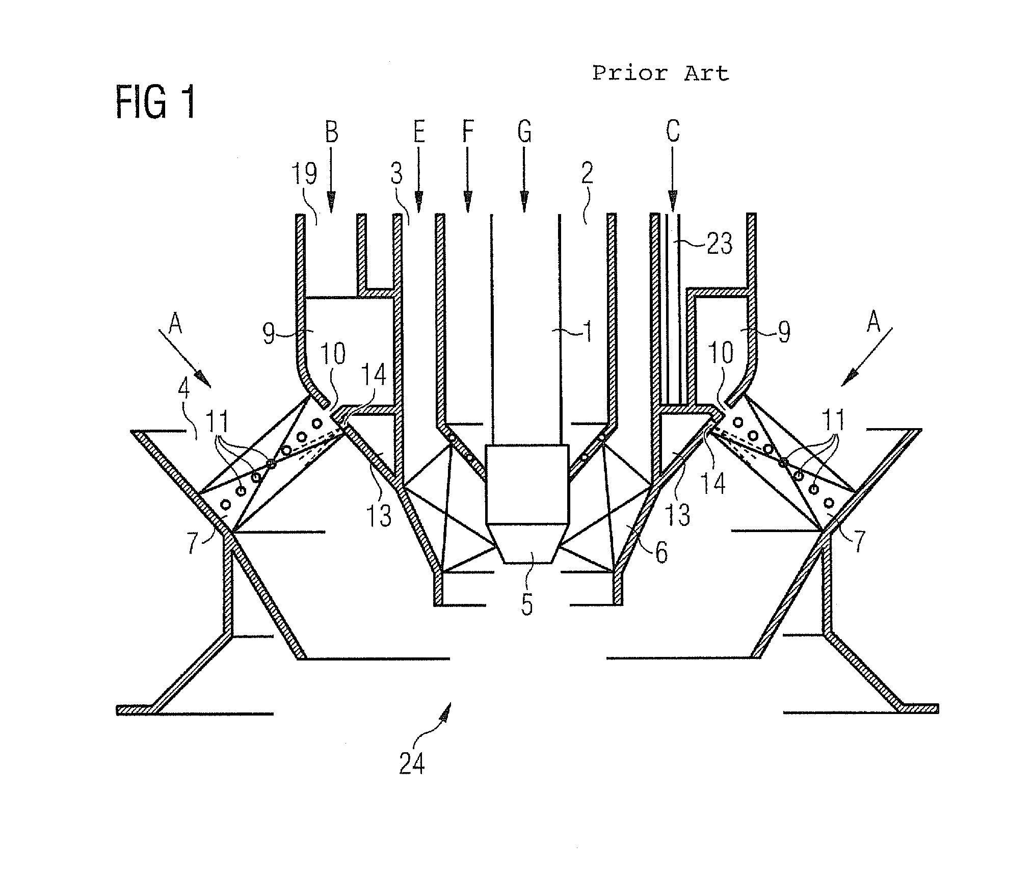
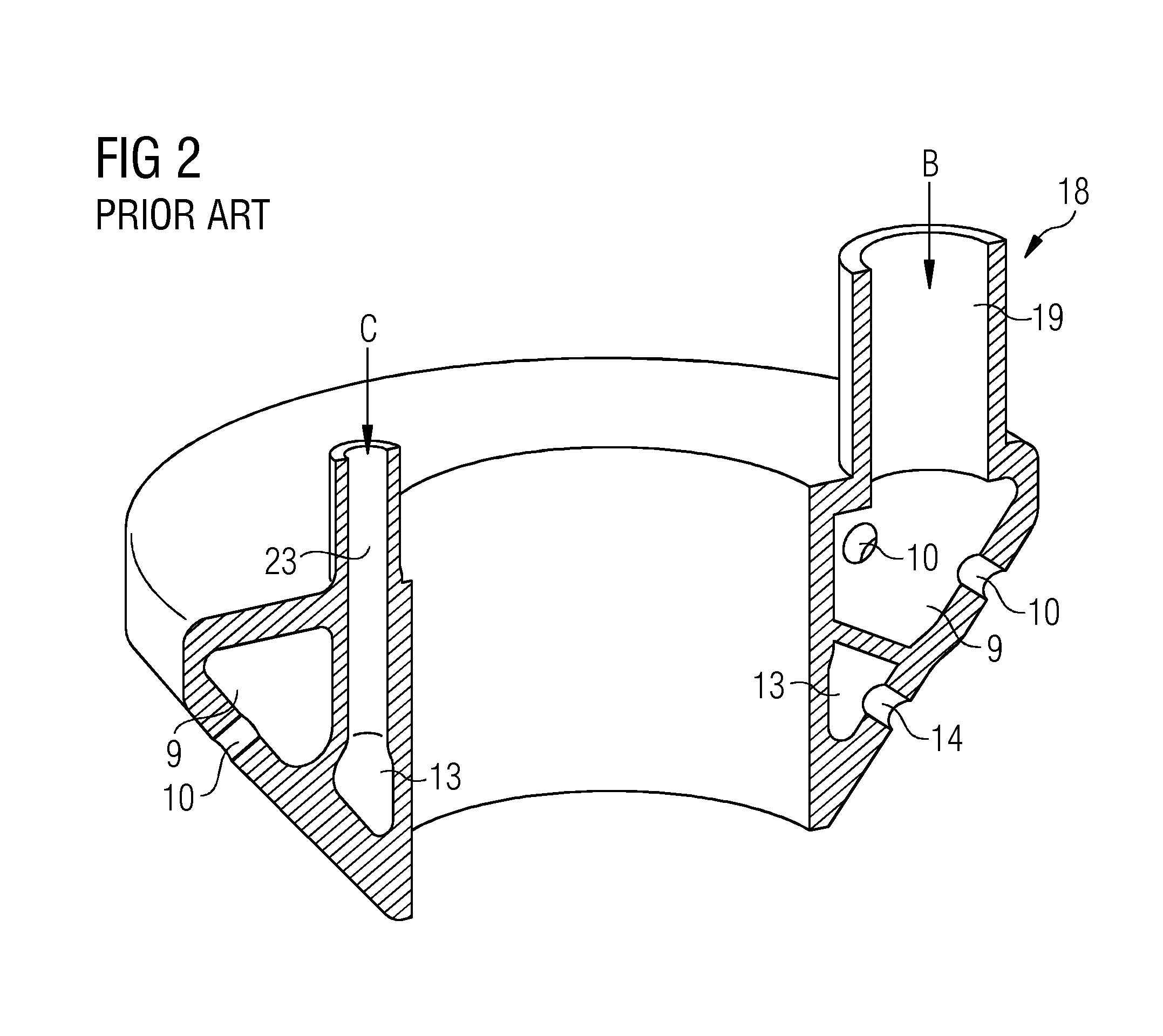
[0021]FIG. 1 shows a burner arrangement according to the prior art, which can optionally be used in conjunction with a number of arrangements of the same type, for example in the combustion chamber of a gas turbine installation.

[0022]It consists of an inner part, the pilot burner system, and an outer part lying concentric thereto, the main burner system. Both systems are suitable for operation with gaseous and / or liquid fuels in any combination. The pilot burner system comprises a central oil supply 1 (medium G) with an oil nozzle 5 disposed at its end and an inner gas supply duct 2 (medium F) disposed concentrically around the central oil supply 1. This in turn is surrounded by an inner air supply duct 3 (medium E) disposed concentrically around the axis of the burner. A suitable ignition system, for which many possible embodiments are known, can be disposed in or on the inner air supply duct 3. This is therefore not illustrated here. The inner air supply duct 3 features a swirl bl...


PUM


Abstract

A burner assembly for a firing system for firing fluidic fuels is provided. The burner assembly has a burner hub, an air inlet channel and a fuel inlet channel, wherein the fuel inlet channel is at least partially designed in the burner hub. A screening wall is arranged in the fuel inlet channel. The screening wall is spaced apart from a wall of the fuel inlet channel so that an intermediate space is formed between the wall of the fuel inlet channel and the screening wall. A sleeve is equipped with at least one radial positioning means that ensures a clearance of the sleeve from the wall of the fuel inlet channel. The at least one radial positioning means of the sleeve is designed as a positioning projection arranged in a circular manner, protruding out radially.

Description

CROSS REFERENCE TO RELATED APPLICATIONS[0001]This application is the US National Stage of International Application No. PCT / EP2010 / 053060 filed Mar. 11, 2010, and claims the benefit thereof. The International Application claims the benefits of European Patent Application No. 09155441.0 EP filed Mar. 18, 2009. All of the applications are incorporated by reference herein in their entirety.FIELD OF INVENTION[0002]The invention relates to a burner arrangement for firing fluidic fuels and in particular a burner arrangement for a gas turbine installation.BACKGROUND OF INVENTION[0003]Burner arrangements for firing fluidic fuels are used inter alia to operate gas turbines in power plants and other large machine applications. What are known as dual fuel burners are used in particular here, being provided optionally or combined to fire liquid and gaseous fuels, for example natural gas and fuel oil.[0004]The burner arrangements have correspondingly large dimensions and feature a complex struct...

Claims


Application Information

Patent Timeline
Patent Type & Authority Patents(United States)
IPC IPC(8): F23R3/28
CPCF23R3/283F23D2211/00F23D2900/00018
Inventor JORDAN, KARSTENKRIEGER, TOBIAS
Owner SIEMENS AG
Learn More