
Photoluminescent objects

a technology of photoluminescent objects and compositions, applied in the field of photoluminescent compositions or structures, can solve the problems of environmental instability of photoluminescent phosphors, limited indoor applications limited use of metal sulfide pigments, so as to enhance the stability of one or more fluorescent materials, and enhance the stability of one or more fluorescent layers

Inactive Publication Date: 2015-06-16
PERFORMANCE INDICATOR LLC
View PDF16 Cites 355 Cited by
  • Summary
  • Abstract
  • Description
  • Claims
  • Application Information

AI Technical Summary

Benefits of technology

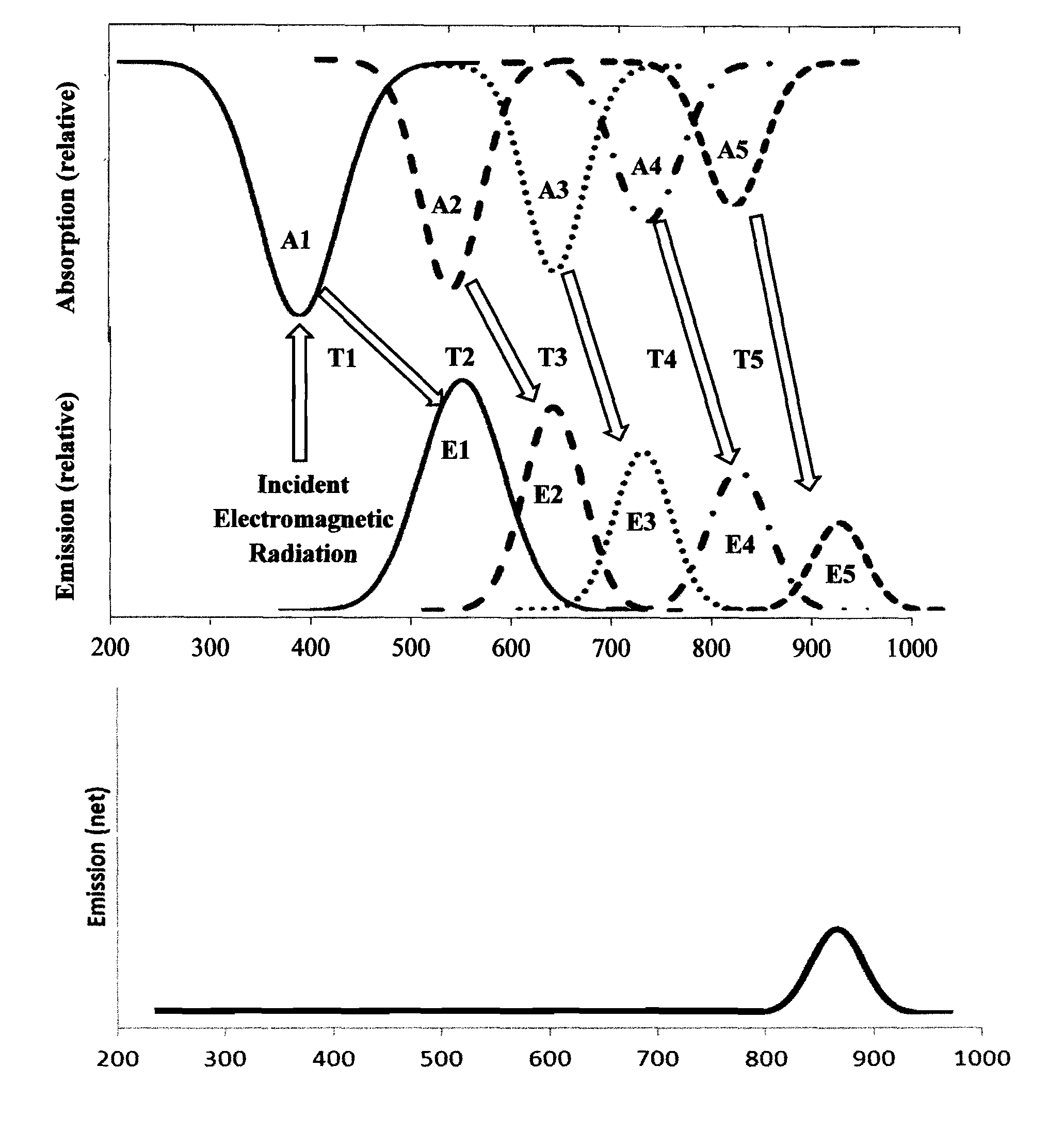
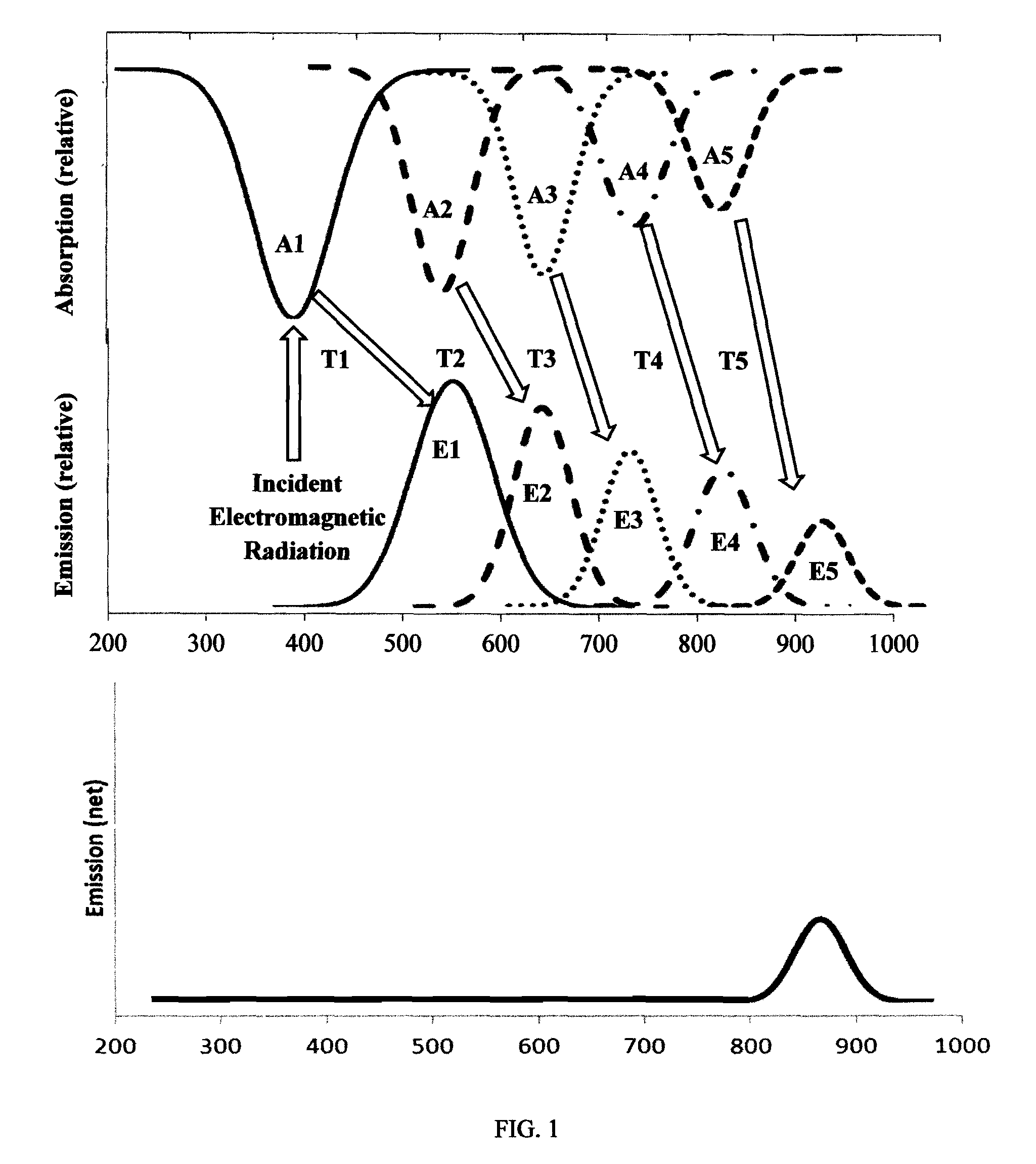
[0010]The present teachings further provide for a method for generating long-persistent luminescence. The method comprises providing a low rare earth mineral photoluminescent structure that comprises a phosphorescent layer and one or more fluorescent layers. The phosphorescent layer comprises one or more phosphorescent materials having substantially low rare earth mineral content of less than about 2.0 weight percent with an absorption spectrum that at least partially overlaps with incident electromagnetic radiation, whereas the one or more fluorescent layers have an absorption spectrum that overlaps with at least a portion of a primary emission. The low rare earth mineral photoluminescent structure is subsequently exposed to incident electromagnetic radiation and the phosphorescent layer substantially converts at least a portion of incident electromagnetic radiation to the primary emission being of long-persistent luminescence, and the one or more fluorescent layers wholly or partially convert at least the primary emission to a secondary emission being of long-persistent luminescence. The phosphorescent layer may further comprise one or more other phosphorescent materials having an absorption spectrum that at least partially overlaps with at least one of incident electromagnetic radiation, the emission spectrum of the one or more phosphorescent materials, or the secondary emission. In addition, the one or more other phosphorescent materials may also have an emission spectrum that at least partially overlaps with the absorption spectrum of the one or more phosphorescent materials. The low rare earth mineral photoluminescent structure may also comprise a substrate that provides base support for the low rare earth mineral photoluminescent structure. The phosphorescent layer may additionally comprise one or more UV absorbers that substantially enhance the stability of the one or more fluorescent layers through absorption of at least a portion of incident ultraviolet electromagnetic radiation. The low rare earth mineral photoluminescent structure may further comprise a UV layer that substantially enhances the stability of the one or more fluorescent layers through absorption of at least a portion of incident ultraviolet electromagnetic radiation. The low rare earth mineral photoluminescent structure may also comprise a reflection layer that redirects at least a portion of radiation emitted in at least one of the phosphorescent layer or the one or more fluorescent layers. The low rare earth mineral photoluminescent structure may further comprise a protective layer that provides at least one of mechanical, chemical, or photolytic durability to the low rare earth mineral photoluminescent structure.
[0011]The present teachings further provide for a low rare earth mineral photoluminescent composition for generating long-persistent luminescence. The low rare earth mineral photoluminescent composition comprises one or more phosphorescent materials that substantially convert at least a portion of incident electromagnetic radiation to a primary emission being of long-persistent luminescence. The one or more phosphorescent materials of the present teachings have substantially low rare earth mineral content of less than about 2.0 weight percent with an absorption spectrum that at least partially overlaps with incident electromagnetic radiation. The low rare earth mineral photoluminescent composition also comprises one or more fluorescent materials having an absorption spectrum that overlaps with at least a portion of the primary emission, such that the one or more fluorescent materials wholly or partially convert at least the primary emission to a secondary emission being of long-persistent luminescence. In addition, the one or more phosphorescent materials also substantially enhance the stability of the one or more fluorescent materials. In one aspect, the low rare earth mineral photoluminescent composition may further comprise one or more other phosphorescent materials having an absorption spectrum that at least partially overlaps with at least one of incident electromagnetic radiation, the emission spectrum of the one or more phosphorescent materials, or the secondary emission. In addition, the one or more other phosphorescent materials may also have an emission spectrum that at least partially overlaps with the absorption spectrum of the one or more phosphorescent materials. The low rare earth mineral photoluminescent composition may be disposed into or onto a substrate that provides base support for the low rare earth mineral photoluminescent composition. In an alternative aspect, the low rare earth mineral photoluminescent composition may be disposed onto a reflection layer that redirects at least a portion of radiation emitted in said low rare earth mineral photoluminescent composition. In certain constructions, the reflection layer may additionally function as a substrate that provides base support for the low rare earth mineral photoluminescent composition. The low rare earth mineral photoluminescent composition of the present teachings may also comprise one or more UV absorbers that further substantially enhance the stability of the one or more fluorescent materials through absorption of at least a portion of incident ultraviolet electromagnetic radiation. In other constructions, the low rare earth mineral photoluminescent composition may be disposed onto a surface of one or more fluorescent layers, such that a longer emissive wavelength is produced.
[0012]The present teachings also provide for a method for fabricating a composition for generating long-persistent luminescence. The method comprises incorporating one or more phosphorescent materials having substantially low rare earth mineral content of less than about 2.0 weight percent with an absorption spectrum that at least partially overlaps with incident electromagnetic radiation, and one or more fluorescent materials having an absorption spectrum that overlaps with at least a portion of a primary emission into the composition, the composition being a low rare earth mineral photoluminescent composition. The low rare earth mineral photoluminescent composition, when subsequently exposed to incident electromagnetic radiation, enables the one or more phosphorescent materials to substantially convert at least a portion of incident electromagnetic radiation to the primary emission being of long-persistent luminescence, and the one or more fluorescent materials to wholly or partially convert at least the primary emission to a secondary emission being of long-persistent luminescence. In addition, the one or more phosphorescent materials also substantially enhance the stability of the one or more fluorescent materials. In one aspect, the method of the present teachings may further comprise incorporating one or more other phosphorescent materials into the low rare earth mineral photoluminescent composition, wherein the one or more other phosphorescent materials having an absorption spectrum that at least partially overlaps with at least one of incident electromagnetic radiation, the emission spectrum of the one or more phosphorescent materials, or the secondary emission. In addition, the one or more other phosphorescent materials may also have an emission spectrum that at least partially overlaps with the absorption spectrum of the one or more phosphorescent materials. In yet another aspect, the method of the present teachings may also comprise depositing one or more UV absorbers into the low rare earth mineral photoluminescent composition, wherein the one or more UV absorbers further substantially enhance the stability of the one or more fluorescent materials through absorption of at least a portion of incident ultraviolet electromagnetic radiation.

Problems solved by technology

Unfortunately, such metal sulfide photoluminescent phosphors were shown to be environmentally unstable and exhibited photolytic instability.
Consequently, such metal sulfide pigments have been limited to indoor applications, as well as applications that do not require luminescence for prolonged periods of time.
However, the green aluminate phosphor contains a substantial amount of rare earth minerals, which require excavation and purification that create pollution and environmental problems.
It is this reliance on substantial amounts of rare earth minerals that results in the cost of such phosphor to be highly unstable and dependent on uncontrollable factors.
In addition, as a result of its host material, such phosphor is shown to be unstable in the presence of water, as well as in high humidity environments.

Method used


Image

  • Photoluminescent objects
  • Photoluminescent objects
  • Photoluminescent objects

Examples


example 1

Preparation of Low Rare Earth Mineral Photoluminescent Composition (Characterized as 2 in FIG. 5)

[0092]A formulation containing 100 parts of a commercial solvent-borne polyurethane, such as Mace resin 107-268, having 50% solids polyurethane in Toluene / Isopropanol, and 125 parts of a blue green long persistent phosphor, such as Performance Indicator PI-B20, was prepared and mixed at room temperature. To this solution was added 12.5 parts of a dye solution containing 0.1% Lumogen Yellow F083 in dioxolane and the mixture was stirred at room temperature until fully dissolved to yield a low rare earth mineral photoluminescent composition.

example 2

Preparation of One or More Fluorescent Layers (Characterized as 10 in FIGS. 6-10)

[0093]A formulation containing 100 parts of an acrylic copolymer, such as Lucite Elvacite 2014, 65 parts toluene, 6.5 parts plasticizer, such as Plasthall P670, 0.9 parts wetting agent, such as Noresil S-900, 0.3 parts dye Lumogen Yellow F-083, 0.0375 parts dye Lumogen Yellow F-170, and 0.0375 parts dye solvent blue 38 was prepared and stirred at room temperature. The formulation was coated on release base at 10 mils or 250 microns wet thickness and dried at 35° C. for 4 hours and then at 80° C. for an additional 12 hours (for ensuring low residual solvent) to yield a 3 mil or 75 micron thick fluorescent layer.

example 3

Preparation of Phosphorescent Layer (Characterized as 8 in FIGS. 6-10)

[0094]A formulation containing 100 parts of a commercial solvent polyurethane, such as Mace resin 107-268, having 50% solids polyurethane in Toluene / Isopropanol, and 125 parts of a blue green long persistent phosphor, such as Performance Indicator PI-B20, was prepared and mixed at room temperature. This formulation was then coated onto release base at 15 mils wet thickness and dried at 35° C. for 4 hours and then at 80° C. for an additional 12 hours to yield 5 mil thick phosphorescent layer.


PUM

PropertyMeasurementUnit
wavelengthsaaaaaaaaaa
wet thicknessaaaaaaaaaa

Abstract

An object comprising a low rare earth mineral photoluminescent structure incorporated onto or into one or more portions of the object, the object being a photoluminescent object is disclosed. Further disclosed is a method for fabricating the object. An object comprising a low rare earth mineral photoluminescent composition incorporated onto or into one or more portions of the object, the object being a photoluminescent object is also disclosed, as well as, a method for fabricating the object.

Description

CROSS-REFERENCE TO RELATED APPLICATIONS[0001]This application is a continuation-in-part of co-pending U.S. patent application Ser. No. 13 / 604,699 filed on Sep. 6, 2012, entitled “LOW RARE EARTH MINERAL PHOTOLUMINESCENT COMPOSITIONS AND STRUCTURES FOR GENERATING LONG-PERSISTENT LUMINESCENCE,” which is incorporated by reference herein in its entirety for all purposes.BACKGROUND OF THE INVENTION[0002]These teachings relate generally to photoluminescent compositions or structures, and more particularly, to the preparation and use of photoluminescent compositions or structures that utilize phosphorescent material(s) having low rare earth mineral content in combination with fluorescent material(s) to generate long-persistent luminescence, that is, for extended durations at desired emissive wavelengths.[0003]Luminescence is the emission of electronic radiation from a molecule in its electronically excited state. The source, generally referred to as the excitation source, used to bring a mo...

Claims


Application Information

Patent Timeline
Patent Type & Authority Patents(United States)
IPC IPC(8): C09K11/77H01J29/38G21K4/00B32B19/00
CPCC09K11/77G21K4/00H01J29/385C09K11/7792B32B19/00B32B27/08B32B27/20B32B27/22B32B27/304B32B27/308B32B27/32B32B27/36B32B27/365B32B27/40B32B2264/105B32B2307/4026B32B2307/422B32B2437/02B32B2471/00B32B2607/02
Inventor KINGSLEY, EDWARD D.AGRAWAL, SATISH
Owner PERFORMANCE INDICATOR LLC
Learn More