
Liquid filtration media, filter elements and methods

a technology of filter media and liquid fuel, which is applied in the direction of fuels, filtration separation, and separation processes, etc., can solve the problems of unacceptable particle levels passing through the filter media, damage to the engine, and detrimental to engine performance, so as to improve handling, controllable pore size, and improve the effect of permeability and efficiency

Active Publication Date: 2015-06-16
DONALDSON CO INC
View PDF72 Cites 30 Cited by
  • Summary
  • Abstract
  • Description
  • Claims
  • Application Information

AI Technical Summary

Benefits of technology

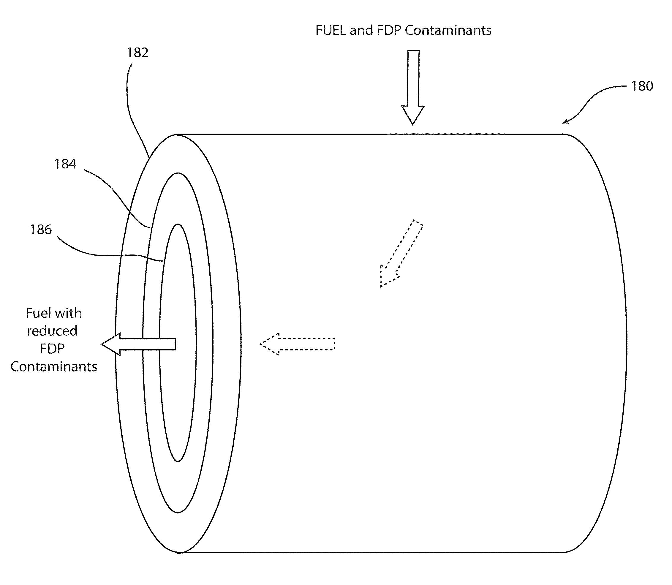
[0008]In a first example embodiment, the filter media comprises an upstream layer of filter media and a downstream layer of filter media. The upstream layer of filter media contains thermally bonded polymeric bicomponent fibers and glass fibers. The downstream layer of filter media comprises cellulose fibers. In this example embodiment, the upstream layer of media containing bicomponent and glass fibers can be laminated to the downstream cellulose media. The upstream layer of media containing the bicomponent and glass fibers has been shown to remove fuel degradation products in a manner such that filter life is preserved, or even extended, relative to prior art filter media. The downstream cellulose layer serves a dual role as a support layer for the upstream filter layer, while also functioning to remove hard particles from the fuel stream. The upstream removal of the fuel degradation products avoids fouling of the downstream cellulose layer with the fuel degradation products, thereby allowing the downstream cellulose layer to capture hard particles without premature fouling, despite a tight pore structure. In addition, in certain embodiments the downstream cellulose layer can be constructed with a tighter pore structure than would otherwise be possible without the upstream layer (or layers) of media containing bicomponent and glass fibers, because the upstream layer (or layers) remove fuel degradation products (or fuel contaminant products) that would otherwise prematurely foul the tighter pore structures.
[0010]Media fiber is that fiber that provides primary filtration properties to the media, such as controllable pore size, permeability and efficiency. The media fiber used in accordance with the invention may be, for example, glass fiber or carbon fiber.
[0011]The binder fiber provides support for the media fiber, and adds improved handling, adds greater strength, and results in lower compressibility to the media. The binder fiber may be, for example, a bicomponent fiber. The use of the bicomponent fiber enables the formation of a media layer (or layers) or filter element with no separate resin binder or with minimal amounts of a resin binder. The lack of a resin binder substantially reduces or prevents film formation from the resin binder and also prevents lack of uniformity in the media or element due to migration of the resin to a particular location of the media layer. The use of the bicomponent fiber reduces compressibility, and allows for lower solidity, increases tensile strength and improves bonding of media fiber such as glass fiber and other sub-micron fiber materials that are added to the media layer or filter element. Also, in certain implementations the binder fiber provides improved processability during furnish formulation, sheet or layer formation, and downstream processing: including thickness adjustment, drying, cutting and filter element formation.
[0015]An additional characteristic of the filter media made in accordance with the present invention is that it is relatively incompressible, especially relative to the solidity of the media. In a first example embodiment, the filter media has a compressibility of less than 40 percent at a pressure of 1.24 kg / cm2. In other implementations the filter media has a compressibility of less than 30 percent at a pressure of 1.24 kg / cm2, less than 20 percent at a pressure of 1.24 kg / cm2, and less than 10 percent at a pressure of 1.24 kg / cm2. It will thus be understood that the filter media of the present invention, at least that portion of the media most suitable for FDP removal, will typically have a relatively low solidity as well as a relatively low compressibility (or high stiffness).
[0017]The ratio of max pore size to mean flow pore is often at least 2.5, optionally at least 5.0, and in some implementations greater than 7.5. In certain embodiments, where the mean flow pore is very small and the max flow pore is relatively high, this ratio may be greater than 10.0, and optionally greater than 12.5 or 15. High ratios of the max flow pore to the mean flow pore reflect a wider pore size distribution, which can provide for reduced fouling from FDPs (and related) contaminants.

Problems solved by technology

Such fuels must generally be filtered so as to remove particulate contaminants, which can otherwise create significant problems in engine performance and can result in damage to the engine.
Without such tight pore structures, unacceptable levels of particles can pass through the filter media and detrimentally affect engine performance.
Although melt-blown media can perform adequately in removing particulate contaminants from liquid fuels, the melt-blown media can readily foul from buildup of contaminants other than traditional particulate contaminants.
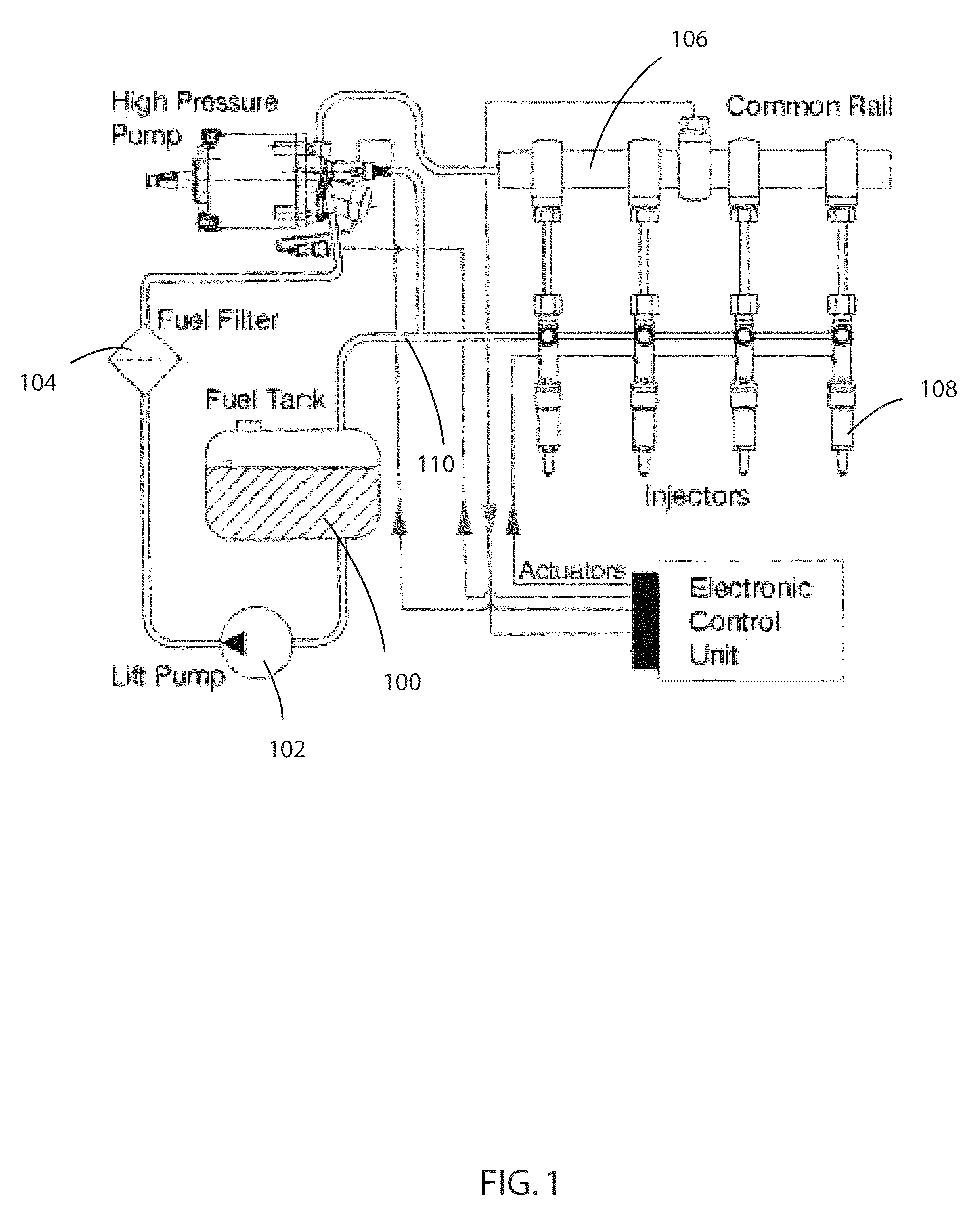
This premature fouling appears to be particularly pronounced in situations where fuel undergoes repeated heating and cooling cycles, such as in common rail systems used on many diesel engines.
In addition to filter-clogging materials generated as a result of heating and cooling cycles, additional sources of contaminants that can reduce fuel filter performance include ingredients found in various biodiesel mixtures.
Finally, even normal aging of fuel, especially when it occurs at heightened temperatures, can result in production of fuel contaminants that further limit fuel filter life due to fouling and clogging of filter media earlier than would otherwise be expected if only hard particle contaminants were present.

Method used


Image

  • Liquid filtration media, filter elements and methods
  • Liquid filtration media, filter elements and methods
  • Liquid filtration media, filter elements and methods

Examples


Embodiment Construction

[0044]The present invention is directed in part to filter media and filter elements for the removal of contaminant material from a liquid fuel stream. The filter elements and media are configured for removal of additional contaminants besides hard particles, these additional contaminants including (for example) waxes, asphaltenes, sterol glucosides, sterol glucosides, sterol glycosides, and fuel degradation products—collectively referred to as fuel contamination products. The filter elements and media allow for improved filter performance and longevity.

[0045]Although existing fuel filtration media, such as melt blown media, can perform adequately in removing particulate contaminants from liquid fuels, the melt blown media can prematurely foul by buildup of contaminants other than traditional particulates. This premature fouling appears to be particularly pronounced in situations where fuel undergoes repeated heating and cooling cycles, such as in common rail systems used on many die...


PUM

PropertyMeasurementUnit
diameteraaaaaaaaaa
mean flow pore sizeaaaaaaaaaa
pore sizeaaaaaaaaaa

Abstract

A filter and filter media configured and arranged for placement in a fuel stream is disclosed. The filter and filter media allow for filtering of liquid fuels, such as diesel fuel. In certain embodiments the filter media includes a media fiber (such as glass) and a binder fiber (such as bicomponent) that combine to create a media structure having low solidity and relatively low compressibility, and which contain a pore structure that avoids premature fouling of the filter by fuel degradation products.

Description

CROSS REFERENCE TO RELATED APPLICATIONS[0001]This application claims priority to U.S. Provisional Patent Application No. 61 / 304,232, filed Feb. 12, 2010, the contents of which are herein incorporated by reference.FIELD OF THE INVENTION[0002]The present invention is directed to filtration media, filter elements, and methods of filtering liquid fuels. In particular, the invention is directed to filtration media for the removal of fuel degradation products (FDPs) and other contaminants from liquid fuels.BACKGROUND[0003]Liquid fuels, such as diesel fuel, are used in internal combustion engines of various configurations and sizes. Such fuels must generally be filtered so as to remove particulate contaminants, which can otherwise create significant problems in engine performance and can result in damage to the engine. Filter media for removal of these particulate contaminants has generally been required to remove very high percentages of particles, necessitating use of filter media with t...

Claims


Application Information

Patent Timeline
Patent Type & Authority Patents(United States)
IPC IPC(8): B01D39/20
CPCB01D39/2024B01D2201/18B01D24/10B01D39/14B01D39/1623B01D39/2017C10L1/04C10L2200/0446B01D2101/005B01D2239/0225B01D2239/1233B01D2239/065B01D2239/1216B01D2239/1266B01D2239/1291B01D39/18
Inventor JONES, DEREK O.DEMA, KEH B.LARSEN, STEPHEN M.MADSEN, MIKE J.DALLAS, ANDREW J.ELSAYED, YEHYA A.YANG, CHUANFANG
Owner DONALDSON CO INC
Learn More