Electricity distribution system

a technology of electric distribution system and distribution circuit, which is applied in the direction of ac network circuit arrangement, battery circuit arrangement, electric apparatus, etc., can solve the problems of increased power loss, decreased power usage efficiency, and the output voltage of the above-mentioned ac-dc converter cannot meet this condition, so as to reduce power loss

Inactive Publication Date: 2015-06-02
PANASONIC INTELLECTUAL PROPERTY MANAGEMENT CO LTD
View PDF12 Cites 0 Cited by
  • Summary
  • Abstract
  • Description
  • Claims
  • Application Information

AI Technical Summary

Benefits of technology

[0010]It is an object of the present invention to provide an electricity distribution system, which can decrease power loss associated with power conversion by means of giving consideration to the wiring configuration of an AC feed line and a DC feed line, and can keep a voltage to ground low, and can satisfy a condition for the voltage to ground within a house.
[0012]In this configuration of the present invention, the system is provided with an AC-DC converter between an AC feed line of a single phase three wire system and a DC feed line. Then, as a three wire system, the DC feed line comprises a neutral wire being commonly connected to a neutral wire of said AC feed line, and further comprises a positive voltage wire having a positive electrical potential to an electrical potential of said neutral wire of said AC feed line, and a negative voltage wire having a negative electrical potential to the electrical potential of said neutral wire of said AC feed line. Therefore, said DC feed line can be installed as an extension of said AC feed line of a single phase three wire system, and house wiring can be easily performed.

Problems solved by technology

Thus, the power loss increases with the power conversion, and the usage efficiency of the power decreases.
Thus, the output voltage of the above-mentioned AC-DC converter can not satisfies this condition.

Method used


Image

  • Electricity distribution system
  • Electricity distribution system
  • Electricity distribution system

Examples


Embodiment Construction

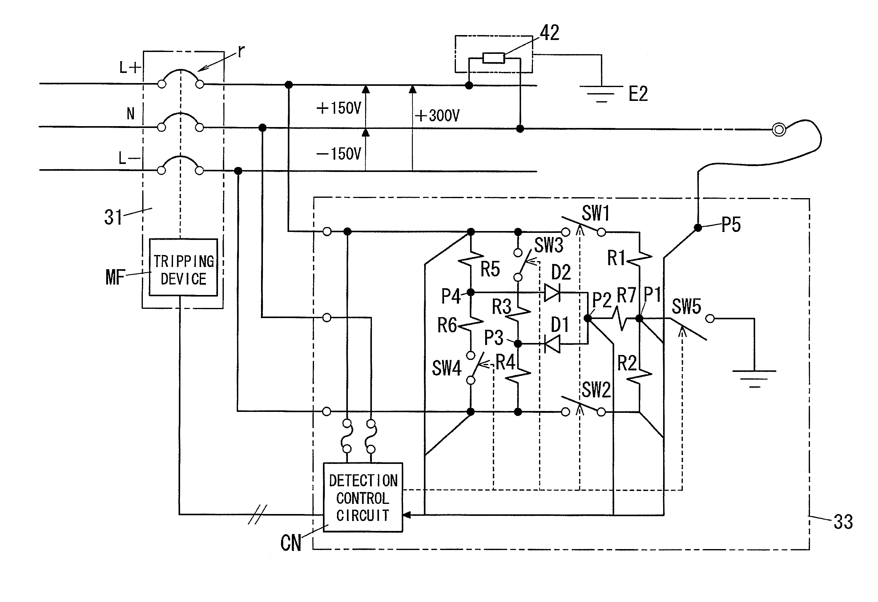
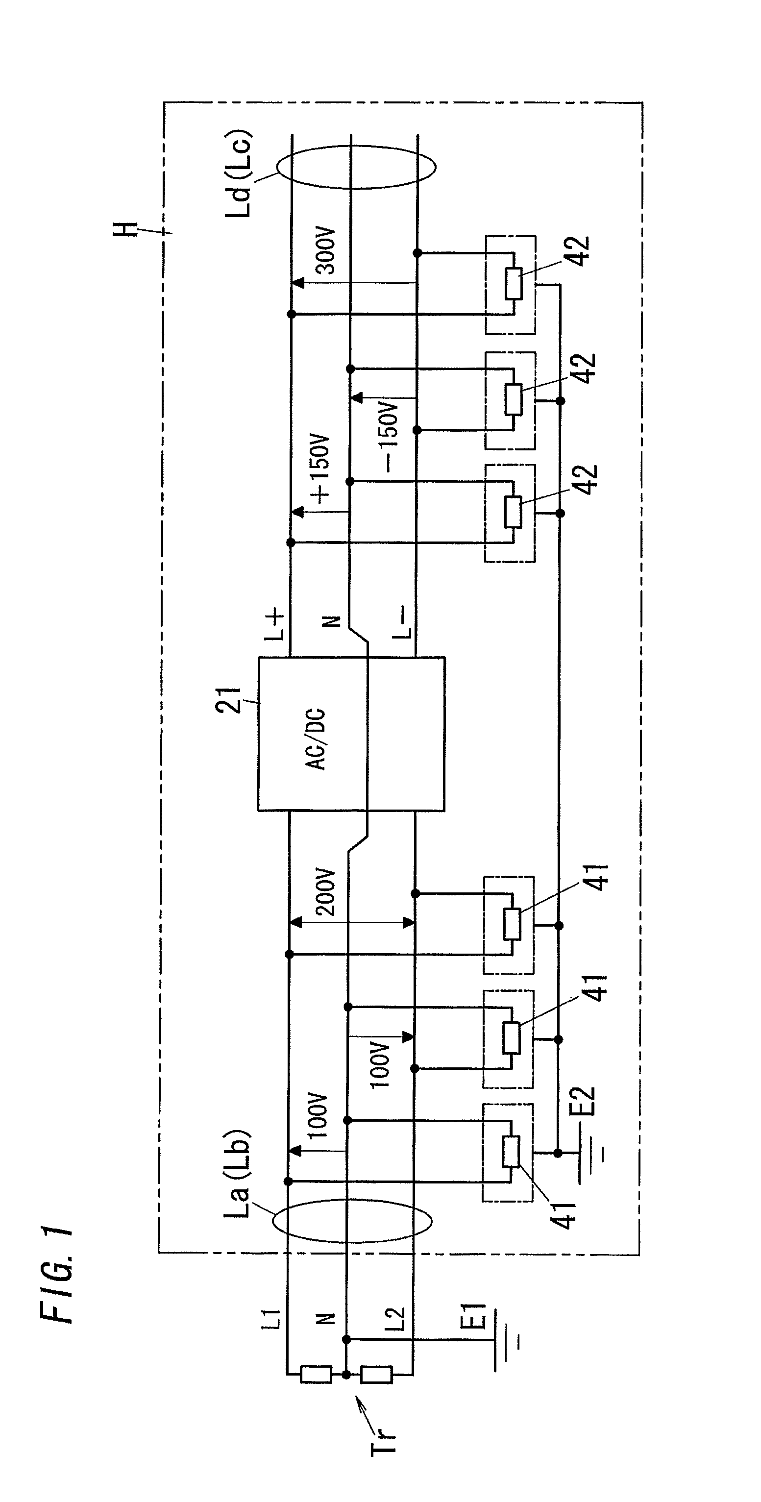
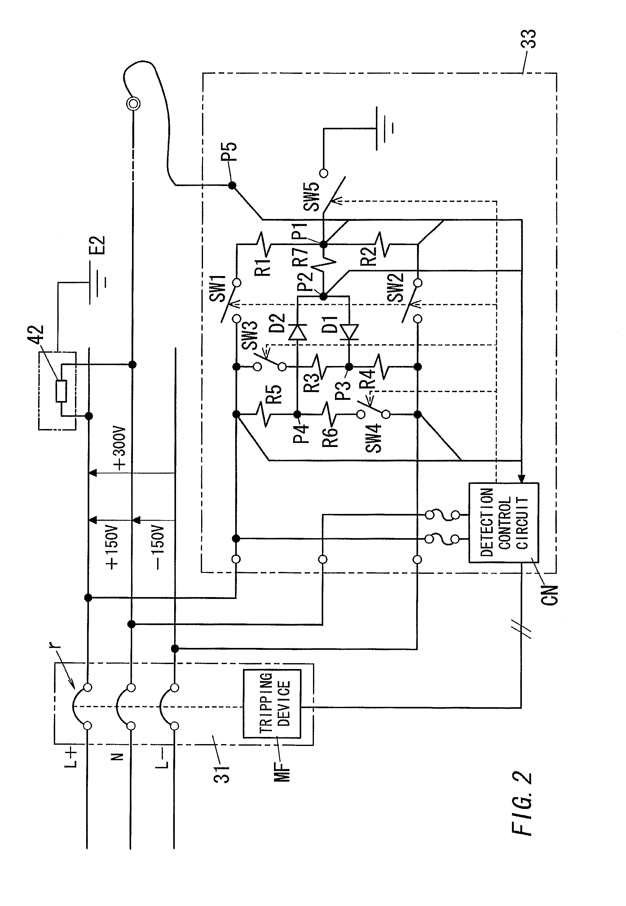
[0021]First, the whole configuration of a distribution system is explained referring to FIG. 3. Here, the distribution system is explained through using a detached house, as one example of a building. However, the same technology can be adopted even in the case where the building is a multiple dwelling house. Then, an electricity distribution system shown in the figure comprises an AC feed line and a DC feed line, and is configured so that the AC feed line receives an AC power from only a commercial power source AC. However, when a dispersed power source DPS comprises a solar power generation facility, the system can be also configured so that the power generated in the solar power generation facility is used for the AC power supplied to the AC feed line.

[0022]It is assumed that the commercial power source AC supplies the AC power through a single phase three wire system. Also, the commercial power source AC is explained in the case that a line voltage between its both voltage wires...


PUM


Abstract

The invention provides an electricity distribution system, which can keep a voltage to ground low, and can commonly detect abnormity, such as an electrical leak etc. produced in AC and DC feed lines. An AC-DC converter 21 is installed between the AC feed line (branch electrical circuit Lb) of a single phase three wire system for supplying the power to AC devices 41, and the DC feed line (main electrical circuit Ld) of a three wire system for supplying the power to DC devices. The DC feed line comprises a neutral wire N commonly connected to a neutral wire N of the AC feed line within the AC-DC converter 21, a positive voltage wire L+ having a positive electrical potential to an electrical potential of its neutral wire N, and a negative voltage wire L− having a negative electrical potential to the electrical potential of its neutral wire N. A voltage of +150 [V] is applied to the positive voltage wire L+, and a voltage of −150 [V] is applied to the negative voltage wire L−.

Description

TECHNICAL FIELD[0001]The invention relates generally to electricity distribution systems and, more particularly, to an electricity distribution system, which comprises an AC feed line and a DC feed line.BACKGROUND ART[0002]In recent years, it has become popular to utilize a dispersed power source, which uses recyclable energy with a low impact on the environment, such as a solar power generation device and a wind energy conversion system. This kind of dispersed power source is configured so as to generate an AC power as the wind energy conversion system and a gas engine power generation device, or is configured so as to generate a DC power. Then, the power-generating capacity of the solar power generation device varies infinitely depending on fluctuation of amount of solar radiation. Therefore, it has been proposed to equalize a supply capability by means of combining the solar power generation device with an electrical power storage unit comprising a secondary battery.[0003]Usually...

Claims


Application Information

Patent Timeline
Patent Type & Authority Patents(United States)
IPC IPC(8): H02J1/00H02J3/00H02H7/26H02J3/02H02J5/00
CPCH02J3/02H02J5/00H02H7/26H02J7/02
Inventor CYUZAWA, TAKAAKI
Owner PANASONIC INTELLECTUAL PROPERTY MANAGEMENT CO LTD
Why Eureka
Try Eureka