
Dual electric driving device and inner speed shifting dual electric motor with clutching and speed reducing driving device thereof

a technology of electric driving device and clutching, which is applied in the direction of coupling, cycle, gearing, etc., can solve the problems of insufficient initial dynamic module, inability to meet the requirements of both energy-saving and electricity-saving, and inability to supply initial dynamic, etc., to prevent power from consuming too much, high dynamic consumption, and easy supply of sufficient initial dynamic to overcome frictional resistan

Active Publication Date: 2015-05-26
HUANG YUNG SUNG
View PDF7 Cites 0 Cited by
  • Summary
  • Abstract
  • Description
  • Claims
  • Application Information

AI Technical Summary

Benefits of technology

The dual electric driving device of this patent allows for a more efficient use of power by using two motors with different speeds or the same speed. This helps to overcome friction and provides enough initial power to start the vehicle. It is particularly useful for applications like electric bicycles where the device is used on roads that require high power consumption. This device prevents excessive power consumption and improves the overall efficiency of the electric ride.

Problems solved by technology

And such a practice inevitably needs to consume a huge amount of power.
However, a huge amount of power is consumed within the process, and if the consumption of electricity goes too much, the problem of insufficient continuity would be easily resulted in, thus the requirement of both energy-saving and electricity-saving could not be satisfied, and the initial dynamic the module provides remains restricted.
This is also a problem of continuity difficult to be solved for electric driving devices such as current electric bicycle and so forth.
It is a pity that the module has the shortage in practice.

Method used


Image

  • Dual electric driving device and inner speed shifting dual electric motor with clutching and speed reducing driving device thereof
  • Dual electric driving device and inner speed shifting dual electric motor with clutching and speed reducing driving device thereof
  • Dual electric driving device and inner speed shifting dual electric motor with clutching and speed reducing driving device thereof

Examples


Embodiment Construction

[0022]The technical contents and characteristics of the present invention will be apparent with the detailed description of a preferred embodiment accompanied with related drawings as follows. For simplicity, the same numerals are used for the same respective elements in the description of the following preferred embodiments and the illustration of the drawings.

[0023]In the following detailed description, example embodiments will now be described more fully hereinafter with reference to the accompanying drawings; however, they may be embodied in different forms and should not be construed as limited to the embodiments set forth herein. Rather, these embodiments are provided so that this disclosure will be thorough and complete, and as those skilled in the art would realize, the described embodiments may be modified in various different ways, all without departing from the spirit or scope of the present invention.

[0024]Except extra definitions, the terminology (including technical an...


PUM


Abstract

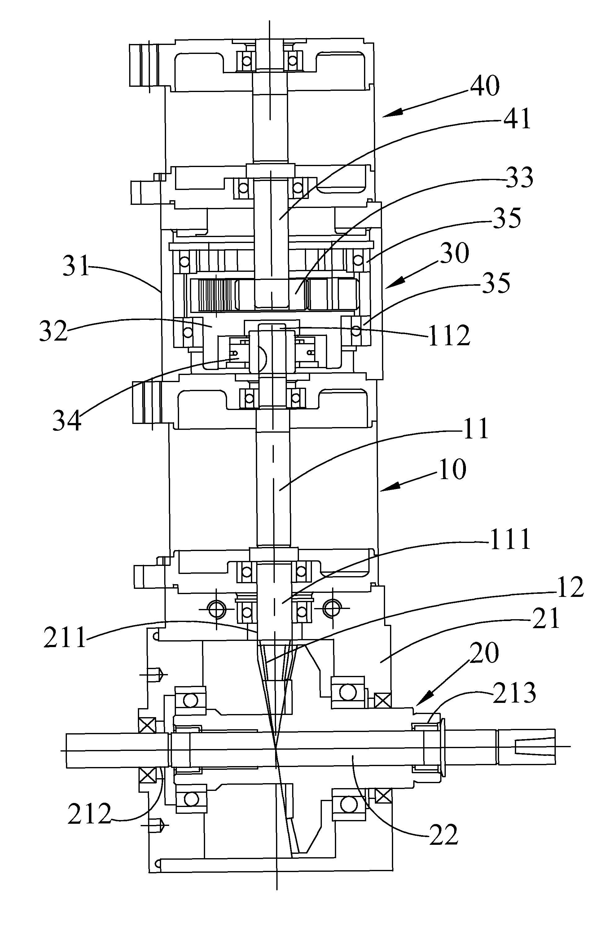
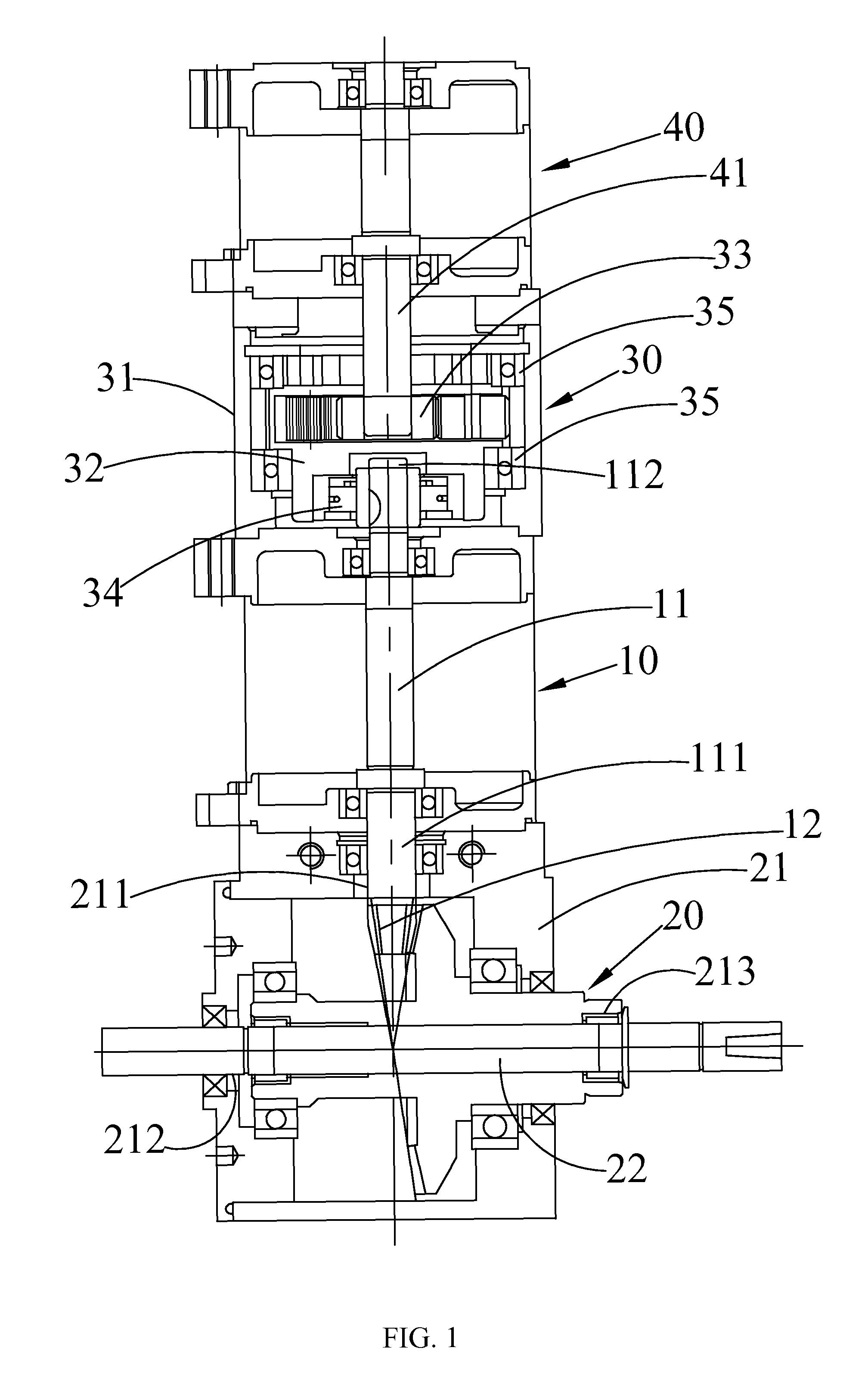
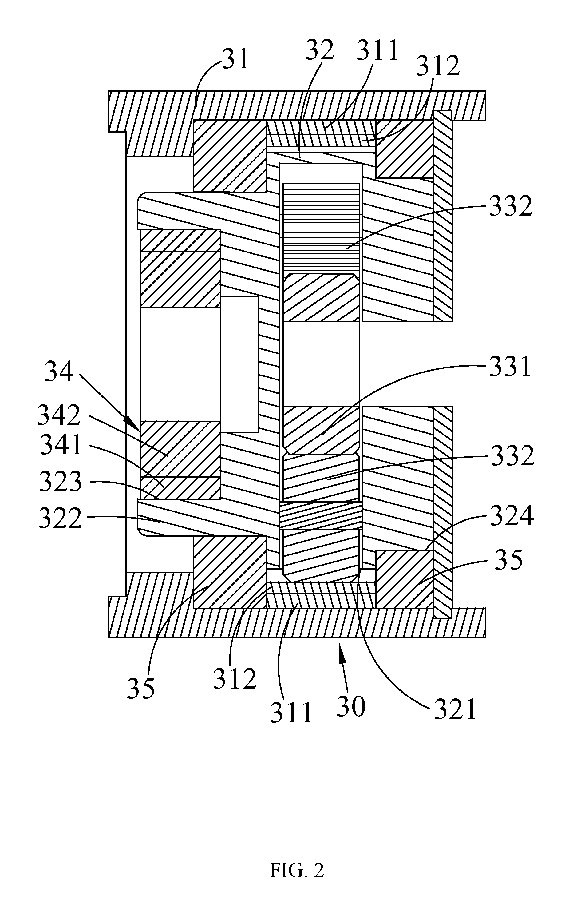
A dual electric driving device, comprising: a main driving motor including a driving rotary shaft, with a shifting transmission gear being mounted on the front end of the driving rotary shaft; an outputting module being correspondingly mounted on the shifting transmission gear, the outputting module including a shifting driving shaft being rotatable by a driving force of the shifting transmission gear; a clutching and speed reducing driving device being correspondingly sleeved onto the back end of the driving rotary shaft of the main driving motor and coaxially rotatable by being engaged with the driving rotary shaft in one single direction; and an accessory driving motor including a driving shaft, the driving shaft being correspondingly mounted through the clutching and speed reducing driving device, and further being able to push the driving rotary shaft in one single direction to rotate by driving the clutching and speed reducing driving device.

Description

CROSS-REFERENCE TO RELATED APPLICATION[0001]This application claims the benefit of Taiwan Patent Application No. 101138133, filed on Oct. 16, 2012, in the Taiwan Intellectual Property Office, the disclosure of which is incorporated herein in its entirety by reference.BACKGROUND OF THE INVENTION[0002]1. Field of the Invention[0003]The present invention generally relates to a dual electric driving device and inner speed shifting dual electric motor with clutching and speed reducing driving device thereof, in particular to an electric driving device applying a dual electric motor as the driving module to optimize the outputting efficiency.[0004]2. Description of the Related Art[0005]Using an electric apparatus such as the motor and so on together with the driving source like the electricity to drive the mechanical force operating is a common driving method based on dynamics. Generally speaking, the electric apparatus, such as the motor, mainly assembles the outputting shaft and the dev...

Claims


Application Information

Patent Timeline
Patent Type & Authority Patents(United States)
IPC IPC(8): F16D3/72B60K1/02B62M6/45B62M6/55B62M6/80F16H37/06
CPCF16H37/065B60K1/02B62M6/55B62M6/45B62M6/80Y10T74/19014B60Y2200/13
Inventor HUANG, YUNG-SUNG
Owner HUANG YUNG SUNG
Learn More