Exhaust system for steam turbine
a steam turbine and exhaust system technology, applied in the direction of machines/engines, stators, liquid fuel engines, etc., can solve the problems of affecting the performance of steam turbines, and unable to provide a sufficient diffuser effect, so as to reduce the amount of pressure loss, improve performance, and suppress the effect of flow turbulen
- Summary
- Abstract
- Description
- Claims
- Application Information
AI Technical Summary
Benefits of technology
Problems solved by technology
Method used
Image
Examples
first embodiment
Configuration
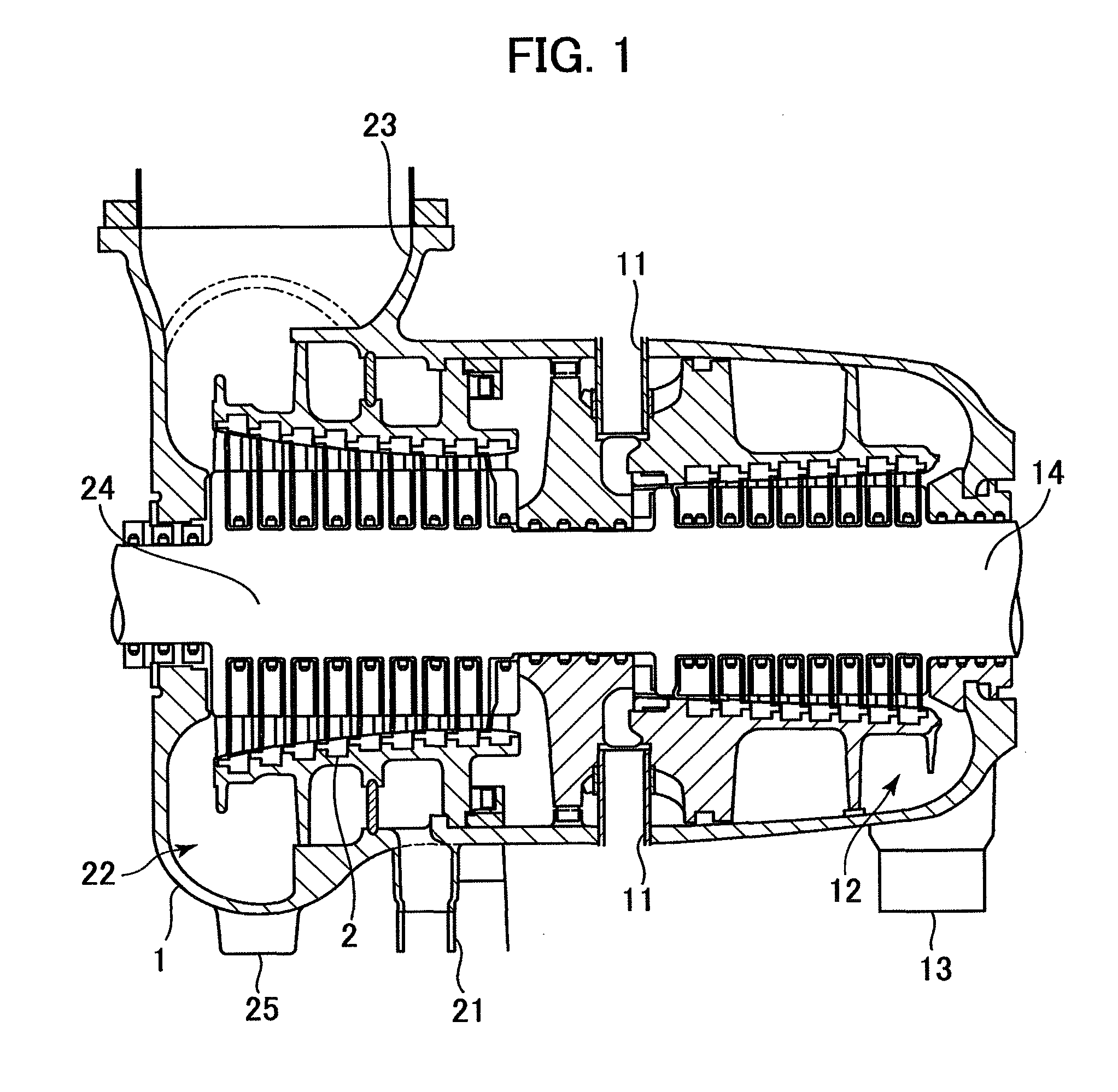
[0037]FIG. 1 is a cross-sectional view illustrating a schematic configuration of high and intermediate pressure portions of a steam turbine embodying the present invention. Steam first flows in from a high pressure inlet 11, performs work in a high pressure turbine stage 14, and flows out into a high pressure exhaust duct 13 via a high pressure exhaust hood 12. The steam flowing out from the high pressure exhaust hood 12 flows through the high pressure exhaust duct 13, a boiler (not shown) and a reheat inlet duct 21 and enters an intermediate turbine stage 24. After doing work at the intermediate turbine stage 24, the steam flows out into an intermediate exhaust duct 23 via an intermediate exhaust hood 22. On the other hand, the steam bled thorough a bleed pipe is led into a heater to be heated.
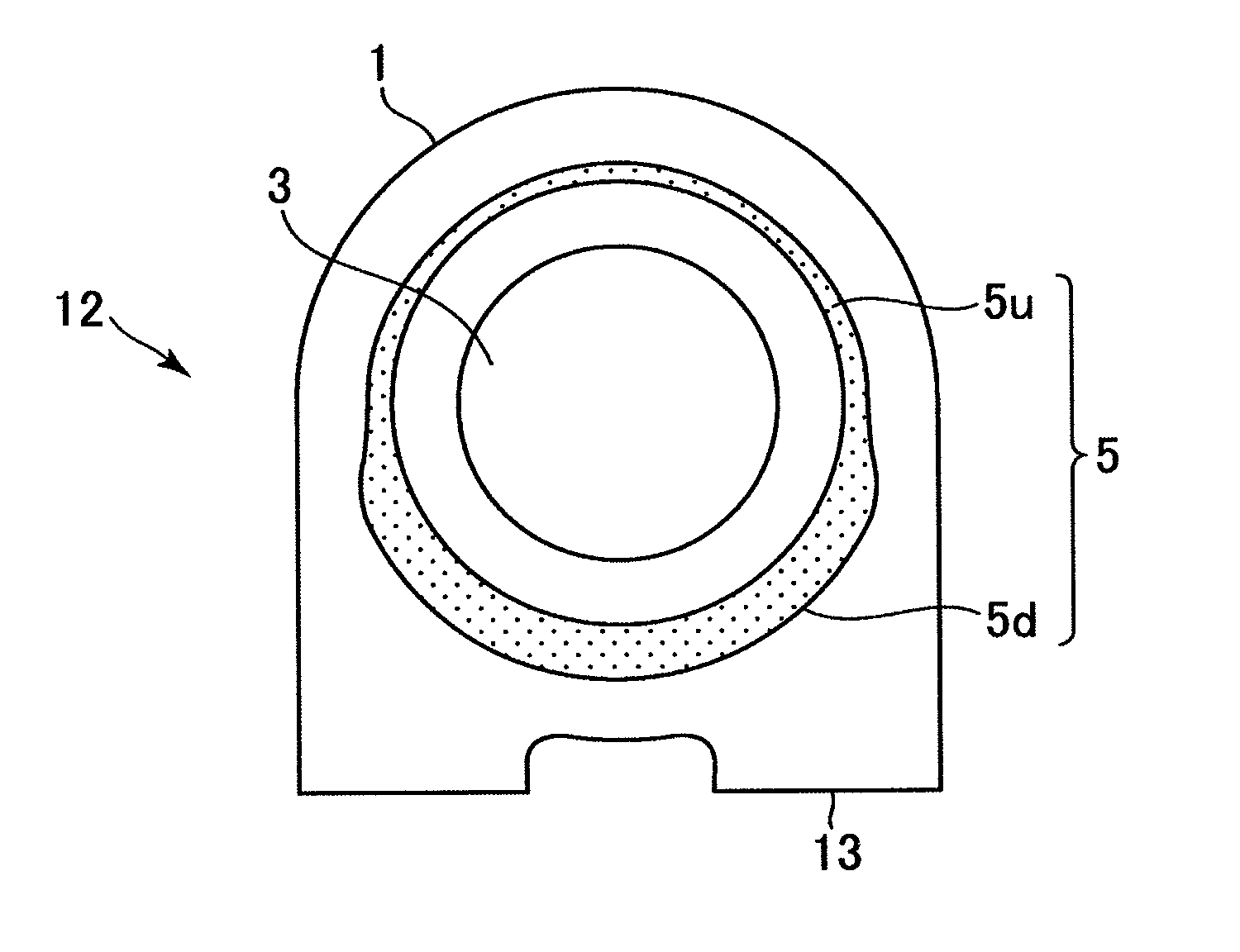
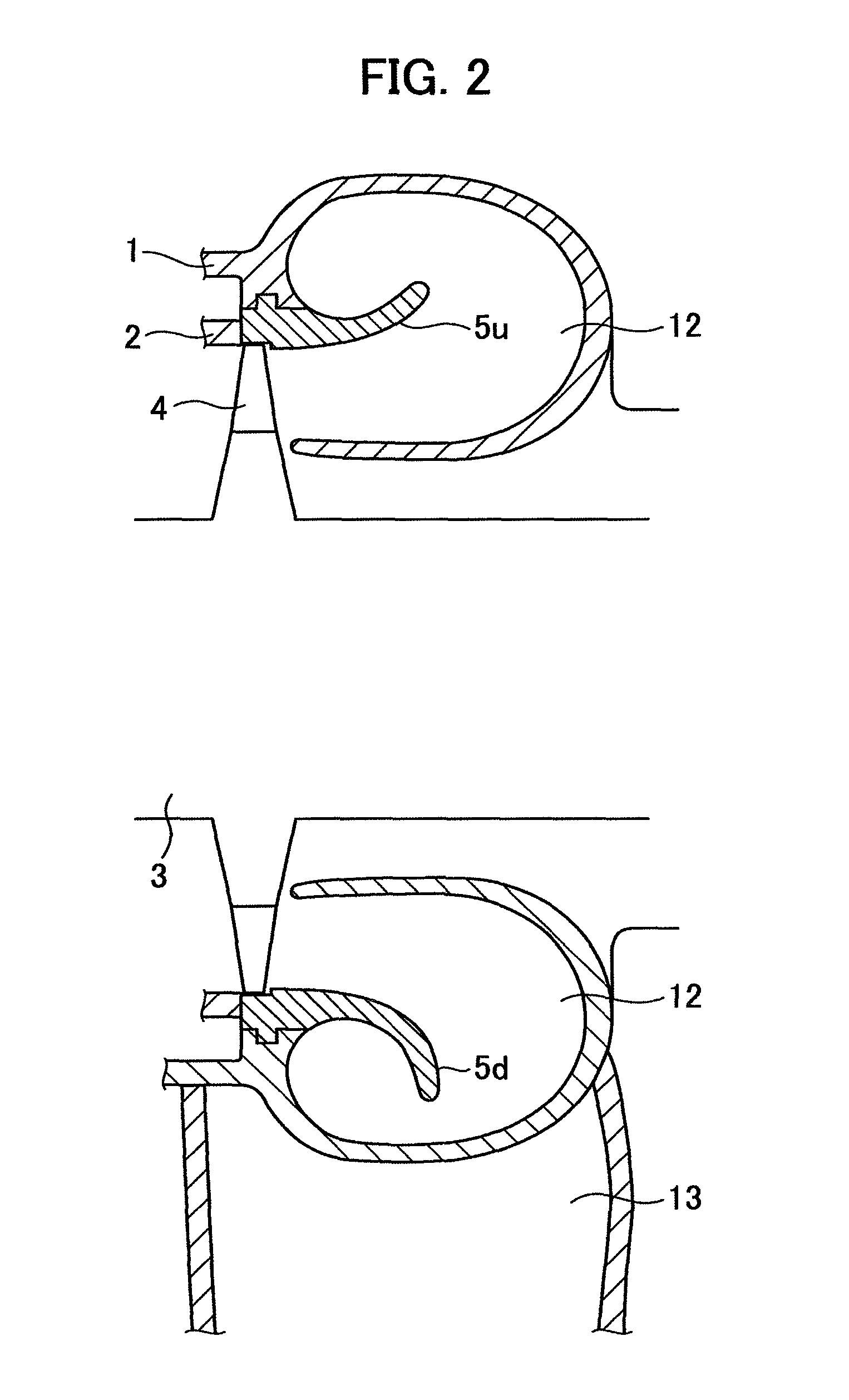
[0038]An exhaust system includes an inner casing 2 covering a turbine rotor 3 of the steam turbine and an outer casing 1 covering the inner casing 2.
[0039]The high pressure exhau...
second embodiment
[0067]In the first embodiment, the portion of the flow guide with θ ranging from 100 to 180° was defined as the downstream flow guide portion 5d having a flow guide occupancy ratio of 0.7. Alternatively, the portion with 0 ranging from approximately 100 to 150°, the area corresponding to the joint portion with the exhaust duct 13, may be set as a most-downstream flow guide portion 5d1. The flow guide occupancy ratio of the most-downstream flow guide portion 5d1 may be set at 0.7.
[0068]FIG. 10 is a graph showing an example of a shape of the flow guide 5B. The flow guide occupancy ratio of the upstream flow guide portion 5u (θ=0 to 80°) is set at 0.4 and that of the most-downstream flow guide portion 5d1 (θ=100 to 150°) is set at 0.7. The flow guide occupancy ratio of the downstream flow guide portion 5d2 (θ=170 to 180°) is set at 0.4 and that of the intervals (θ=80 to 100° and 150 to 170°) varies continuously between 0.4 and 0.7. A transverse cross-sectional view of such flow guide 5...
third embodiment
[0070]The first and the second embodiments showed cases where the present invention is applied to an exhaust hood 12 having two exhaust ducts 13 at the downstream side. The present invention may also be applied to an exhaust hood 12 having one exhaust duct 13.
[0071]FIG. 12 is a graph showing an example of a shape of a flow guide 5C. The flow guide occupancy ratio of the upstream flow guide portion 5u (θ=0 to 120°) is set at 0.4 and that of the downstream flow guide portion 5d (θ=160 to)180° is set at 0.7. The flow guide occupancy ratio of the interval portion (θ=120 to 160°) between them varies continuously from 0.4 to 0.7. A transverse cross-sectional view of the flow guide 5C is shown in FIG. 13.
[0072]The third embodiment can also produce the same effect as that of the first embodiment.
PUM
 Abstract
Description
Claims
Application Information
 - R&D
- Intellectual Property
- Life Sciences
- Materials
- Tech Scout
- Unparalleled Data Quality
- Higher Quality Content
- 60% Fewer Hallucinations
Browse by: Latest US Patents, China's latest patents, Technical Efficacy Thesaurus, Application Domain, Technology Topic, Popular Technical Reports.
© 2025 PatSnap. All rights reserved.Legal|Privacy policy|Modern Slavery Act Transparency Statement|Sitemap|About US| Contact US: help@patsnap.com


