Apparatus and method for driving backlight using scanning backlight scheme, liquid crystal display device and its driving method using scanning backlight scheme
a backlight and scanning backlight technology, applied in the direction of electric digital data processing, instruments, computing, etc., can solve problems such as flicker perception, achieve the effects of reducing consumption power, enhancing the quality of moving images, and reducing flicker
- Summary
- Abstract
- Description
- Claims
- Application Information
AI Technical Summary
Benefits of technology
Problems solved by technology
Method used
Image
Examples
first embodiment
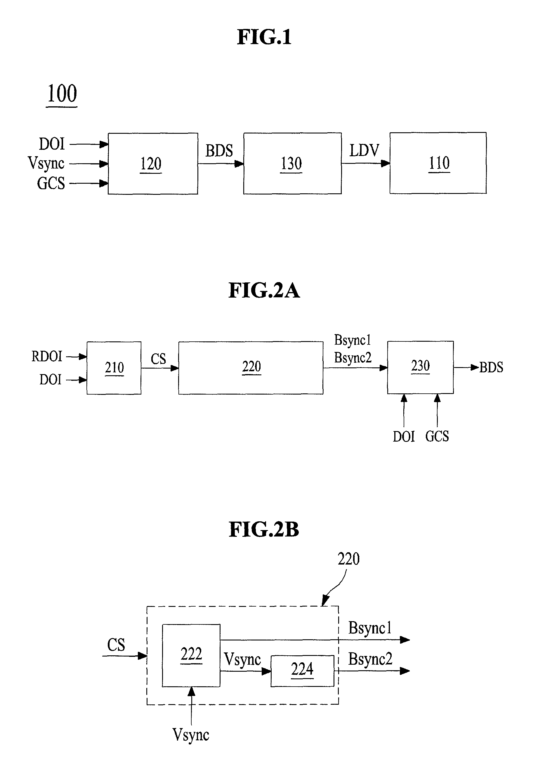
[0040]FIG. 2A is a diagram for describing the backlight controller of FIG. 1. FIG. 2B is a diagram for describing a first embodiment of a backlight sync signal generation unit of FIG. 2A.
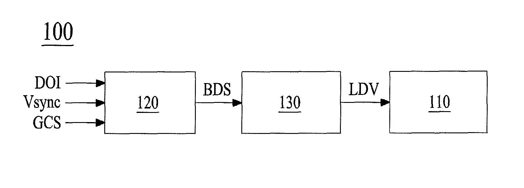
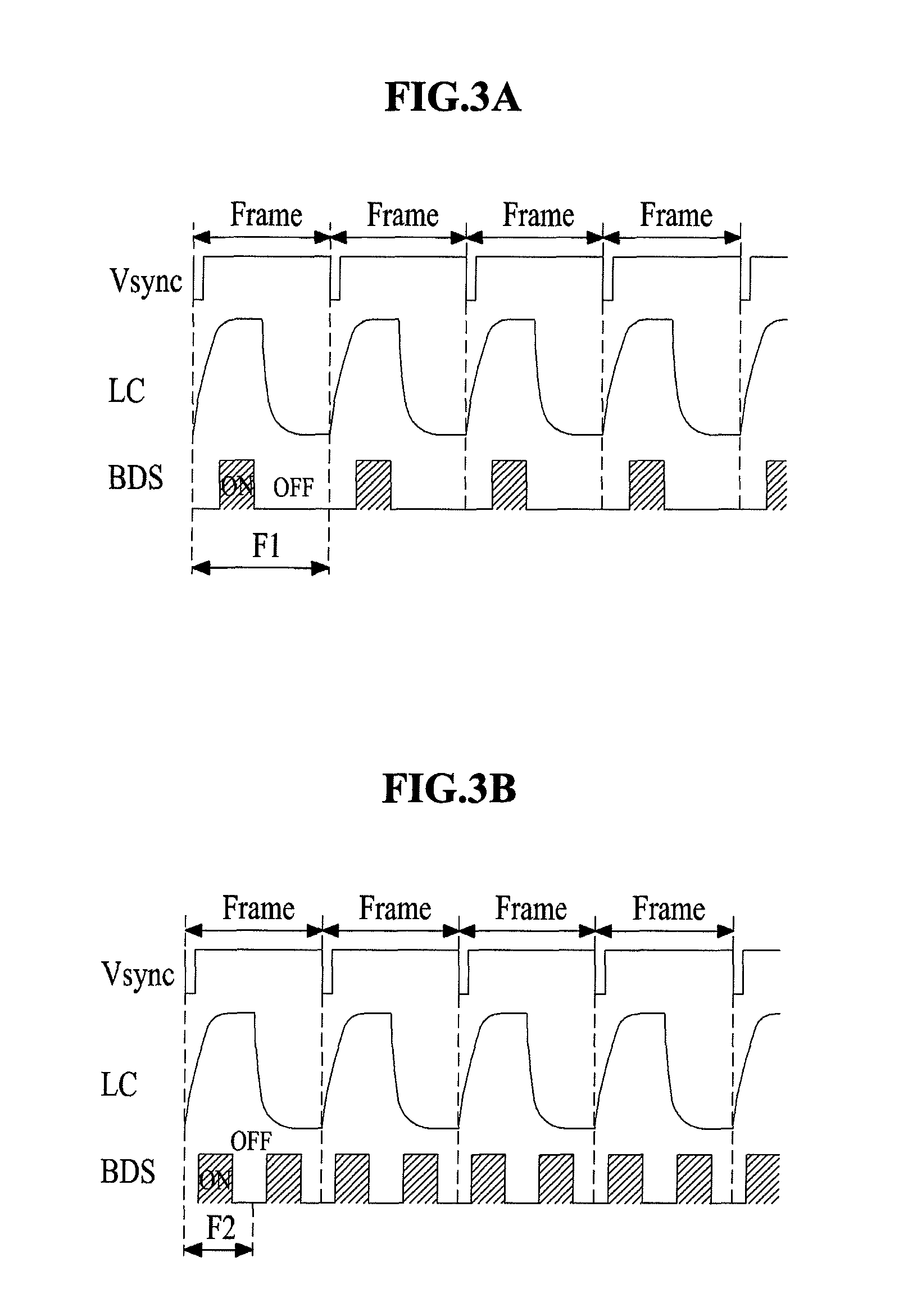
[0041]Referring to FIGS. 2A and 2B, the backlight controller 120 according to the first embodiment generates the backlight dimming signal BDS which has a first frequency equal to that of the frame sync signal Vsync or a second frequency (higher than the frequency of the frame sync signal Vsync) that is generated by multiplying the frequency of the frame sync signal Vsync by at least two times as an example, according to the duty-on information DOI. For example, the frequency of the frame sync signal Vsync may be about 60 Hz, and the second frequency may be about 120 Hz or about 180 Hz. For this end, the backlight controller 120 includes a comparison unit 210, a backlight sync signal generation unit 220, and a dimming signal generation unit 230.
[0042]The comparison unit 210 compares the size of the d...
second embodiment
[0055]FIG. 5A is a diagram for describing the backlight controller of FIG. 1. FIG. 5B is a diagram for describing a backlight sync signal generation unit of FIG. 5A.
[0056]Referring to FIG. 1 and FIGS. 5A and 5B, a backlight controller 120 according to the second embodiment generates a backlight dimming signal BDS having the first frequency equal to that of the frame sync signal Vsync, a backlight dimming signal BDS having a second frequency (which is generated by multiplying the frequency of the frame sync signal Vsync) higher than that of the frame sync signal Vsync, a backlight dimming signal BDS that is gradually increased from the first frequency to the second frequency, or a backlight dimming signal BDS that is gradually decreased from the second frequency to the first frequency. For example, the frame sync signal Vsync may be 60 Hz, and the second frequency may be 90 Hz, 120 Hz, or 180 Hz. For this end, the backlight controller 120 according to the second embodiment includes a...
third embodiment
[0089]FIG. 8 is a diagram for describing the backlight controller of FIG. 1. FIG. 9 is a waveform diagram for describing the dimming signal delay unit of FIG. 8.
[0090]Referring to FIGS. 1, 8 and 9, a backlight controller 120 according to the third embodiment includes a comparison unit 310, a frequency change determination unit 315, a backlight sync signal generation unit 320, a dimming signal generation unit 330, and a dimming signal delay unit 340. Except for the dimming signal delay unit 340, the other elements of the backlight controller 120 according to the third embodiment are configured identically to the backlight controller 120 according to the second embodiment, and thus, their detailed descriptions are not provided. The descriptions of the second embodiment are applied to the other elements of the third embodiment, and like reference numerals refer to like elements.
[0091]The dimming signal delay unit 340 delays a duty-on period ON of the backlight dimming signal BDS suppli...
PUM
 Abstract
Description
Claims
Application Information
 - R&D
- Intellectual Property
- Life Sciences
- Materials
- Tech Scout
- Unparalleled Data Quality
- Higher Quality Content
- 60% Fewer Hallucinations
Browse by: Latest US Patents, China's latest patents, Technical Efficacy Thesaurus, Application Domain, Technology Topic, Popular Technical Reports.
© 2025 PatSnap. All rights reserved.Legal|Privacy policy|Modern Slavery Act Transparency Statement|Sitemap|About US| Contact US: help@patsnap.com


