
Infusion pump and method which inhibits unintended tubing withdrawal

a technology of unintended tubing and infusion pump, which is applied in the direction of intravenous devices, instruments, other medical devices, etc., can solve the problems of not having the degree of precision in fluid delivery that is typically required, the use of ramp valves does not provide the degree of fluid delivery precision that is needed, and it is difficult or impossible to remove the delivery tube from the infusion pump. , to achieve the effect of preventing the free flow of fluid and preventing the function of free flow

Inactive Publication Date: 2015-04-28
WALKMED INFUSION
View PDF29 Cites 7 Cited by
  • Summary
  • Abstract
  • Description
  • Claims
  • Application Information

AI Technical Summary

Benefits of technology

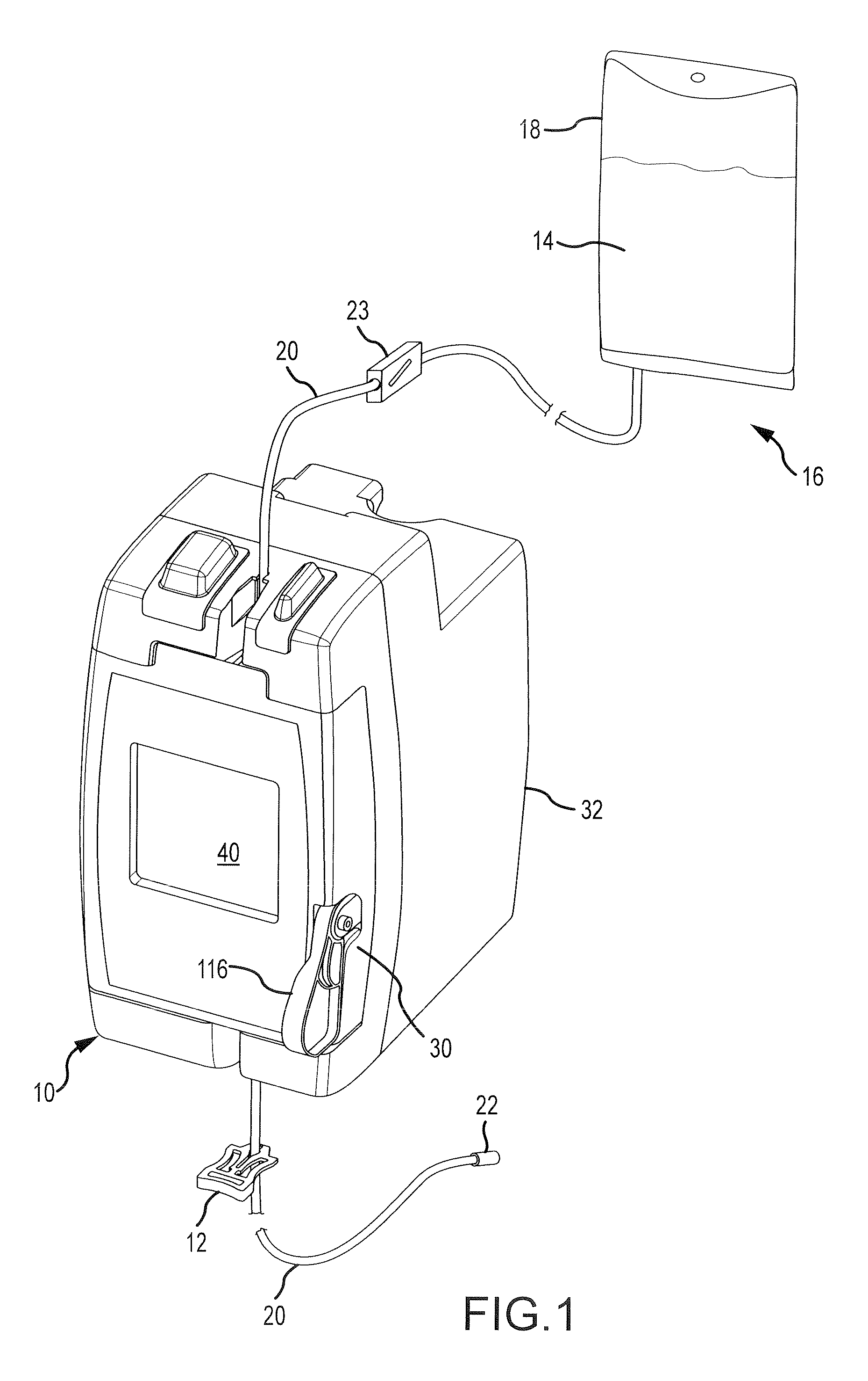
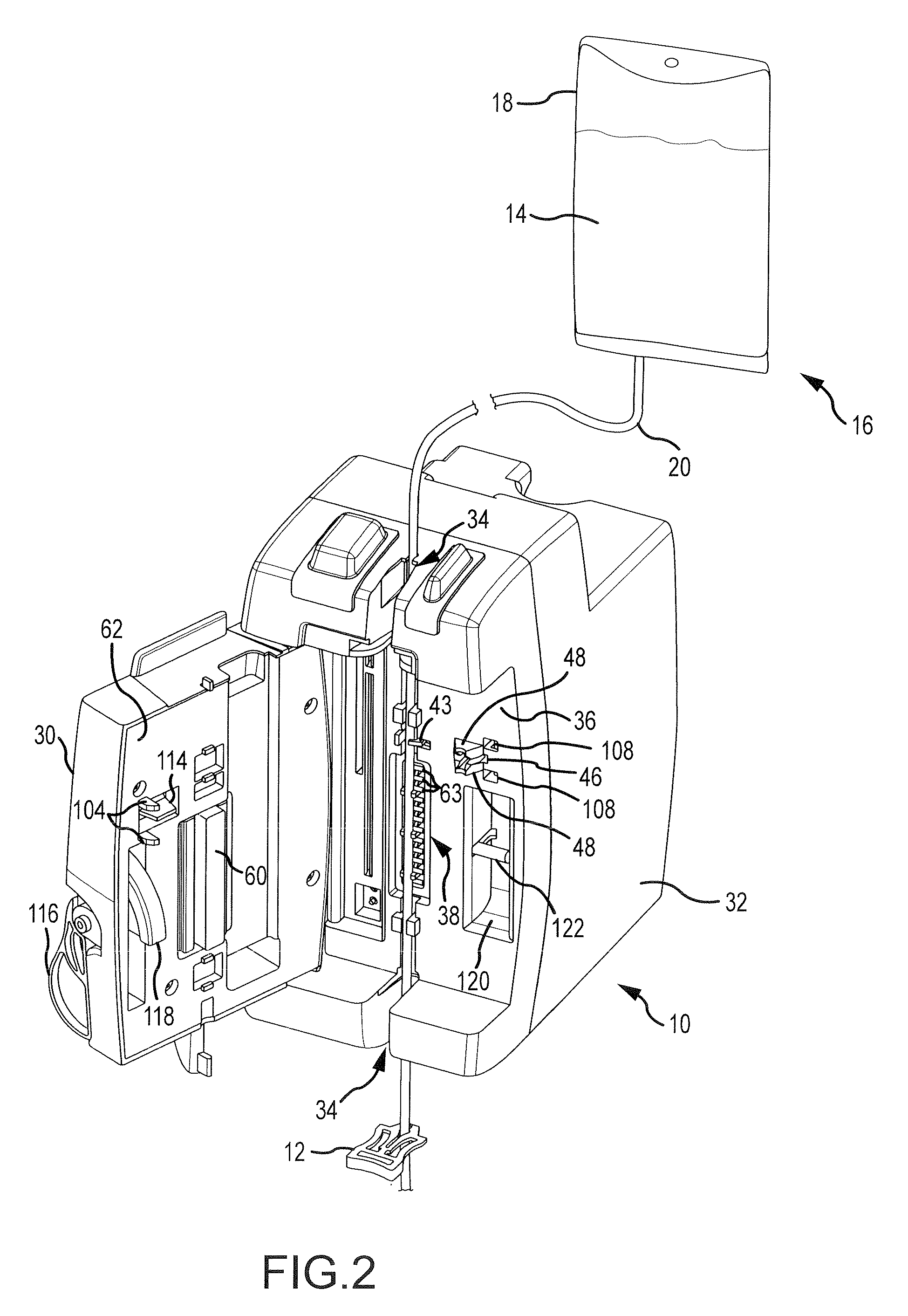
[0015]The present invention uses a slide clamp as an external manual actuator for releasing or opening an internal occlusion clamp within the infusion pump to an open position, to permit removing the delivery tube from the infusion pump. Manually manipulating the slide clamp to release the internal occlusion clamp simultaneously moves the delivery tube into the narrow end of a slot in the slide clamp, thereby preventing the free flow of fluid through a delivery tube whenever the internal occlusion clamp is opened. Thus, the simple expedient of manually manipulating the slide clamp to release the internal occlusion clamp to the open position has the effect of simultaneously occluding the delivery tube and thereby achieving anti-free flow functionality. The slide clamp does not become part of the internal operating mechanism of the infusion pump. When the door of the infusion pump is closed, the door interacts with a peristaltic pump to occlude the tubing, so closing the door also releases the internal occlusion clamp without requiring the presence of the external slide clamp within the infusion pump. Medical personnel must manually move the external slide clamp relative to the delivery tube to deliver fluid to the patient, even after the internal occlusion clamp opens and the infusion pump commences operation. Requiring manual movement of the slide clamp relative to the delivery tube before the pump can operate is a further safety aspect of the invention which prevents unintended fluid delivery to the patient.
[0016]These features of the invention reduce the number of moving parts of the infusion pump, reduce the cost of the pump because of its simpler construction, make the operation of the pump simpler and safer by avoiding the necessity of performing a sequence of complicated steps to occlude and release the delivery tube, thereby enhancing safety by requiring intentional, manual action on the part of medical personnel to deliver fluid to the patient, and permitting medical personnel with less training and experience to successfully operate the infusion pump in a safe and effective manner.
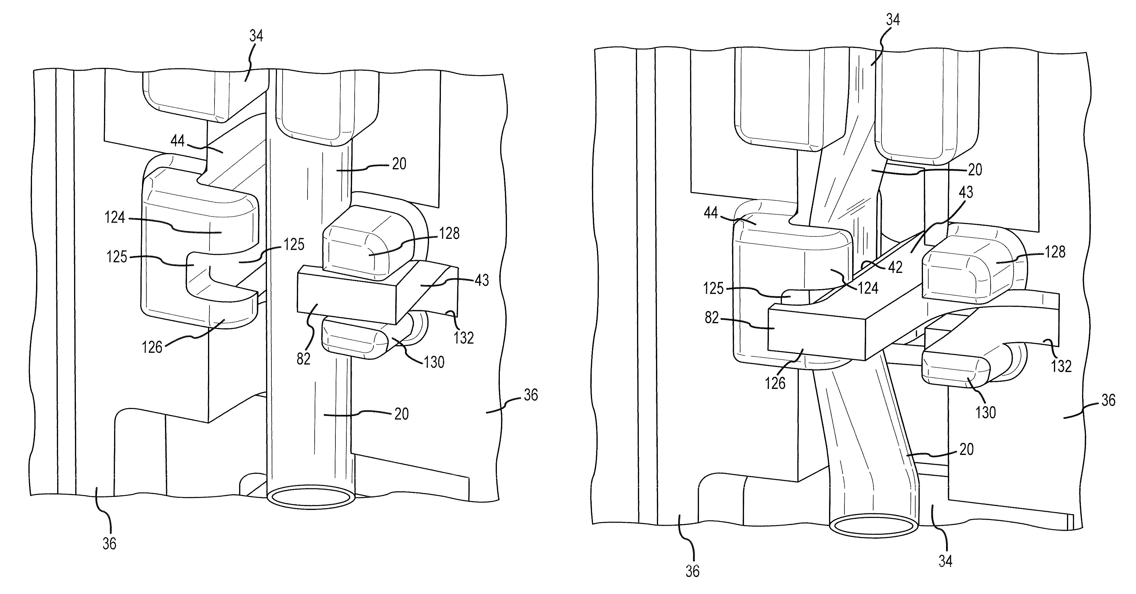
[0018]Another aspect of the invention involves an infusion pump for regulating the flow of medicinal fluid delivered through a delivery tube to a patient. The infusion pump has an internal occlusion clamp which occludes the delivery tube and prevents free flow of the fluid through the delivery tube when in an occluding position and which opens the delivery tube to allow the flow of fluid through the delivery tube when in a non-occluding position. The infusion pump comprises a tubing channel in which a first portion of the delivery tube is located. An anvil is located on one side of the tubing channel, and the anvil has a restraint surface facing the tubing channel and against which the delivery tube is compressed and occluded when the occlusion clamp is in the occluding position. A compression edge of the occlusion clamp faces the tubing channel on the opposite side of the tubing channel from the restraint surface. The compression edge moves into adjacency with the restraint surface to compress and occlude the delivery tube between the compression edge and the restraint surface when the occlusion clamp is in the occluding position. The compression and edge moves away from the restraint surface to open the delivery tube when the occlusion clamp is in the non-occluding position. A front panel has an opening from which a portion of the compression edge extends outward from the front panel. An obstruction protrusion is located adjacent to the opening and extends outward from the front panel a distance at least equal to the distance which the portion of the compression edge extends outward from the front panel. The obstruction protrusion resists the application of exterior physical force on the portion of the compression edge to inhibit unintended forced movement of the occlusion clamp from the occluding position toward the non-occluding position.

Problems solved by technology

Although the ramp valve is useful and sufficiently accurate for some applications, it is not a fully reliable metering device.
In addition, the use of a ramp valve does not typically provide the degree of precision in fluid delivery necessary in many medical situations.
Opening the door results in the internal occlusion clamp clamping the delivery tube, making it very difficult or impossible to remove the delivery tube from the infusion pump.
Even short times of unrestricted gravity flow can introduce potentially dangerous amounts of the medicinal fluid into the bloodstream of the patient, since the flow rate through the operating infusion pump is typically much less than the gravity-induced free flow rate when the delivery tube is not restricted.
Occasionally when it is necessary to remove the delivery tube from the infusion pump, the tubing set may remain connected to the patient, giving rise to the possibility that the fluid will free-flow by gravity into the patient in an uncontrollable manner.
Although unusual, medical personnel may become distracted and fail to close the external clamp.
Medical personnel which do not have the necessary level of experience and training may simply fail to recognize the need to close the external clamp when the delivery tube is removed from the infusion pump while the delivery tube remains connected to the patient.
Executing the necessary sequence of closing the external clamp before removing the delivery tube from the infusion pump may also increase the risk that relatively inexperienced medical personnel may make a mistake in the sequence of actions required.
Because of the potential for human error when using an infusion pump, certain medical standards and accreditation organizations require that infusion pumps have built-in, automatic anti-free flow capabilities.
Some of those anti-free flow mechanisms are subject to unintended manipulation in such a way that the delivery tube can be removed from the infusion pump without occluding the delivery tube, thereby defeating the anti-free flow capability.
Regardless of the level of success in preventing gravity flow, almost all of the previous infusion pumps which possess anti-free flow capability are of considerably increased cost and complexity.
The increased complexity has also increased the risk of mechanical failure, with the attendant possibility of downtime of the equipment leading to the unavailability of the equipment.
The increased complexity also creates an increased risk of successfully defeating the anti-free flow capability, out of a lack of knowledge of the proper functionality of the system or from good faith attempts to remove the delivery tube under appropriate circumstances but using inappropriate techniques.
A variety of other types of anti-free flow mechanisms are also used in infusion pumps, but these other types of anti-free flow mechanisms do not employ slide clamps.

Method used


Image

  • Infusion pump and method which inhibits unintended tubing withdrawal
  • Infusion pump and method which inhibits unintended tubing withdrawal
  • Infusion pump and method which inhibits unintended tubing withdrawal

Examples


Embodiment Construction

[0037]An infusion pump 10 and a slide clamp 12 which embody the present invention are shown in FIG. 1. The infusion pump 10 precisely meters a flow of medicinal fluid 14 through an intravenous tubing set 16 to a patient (not shown). The tubing set 16 includes a flexible and collapsible bag 18 which stores the fluid 14, and a delivery tube 20 which conducts the fluid 14 from the bag 18 to a connector 22. The connector 22 connects to a needle (not shown) inserted into a vessel, typically a vein of a patient, or to a complementary connection of a conventional vessel access device attached to the patient. A conventional ramp or roller clamp 23 is connected to the delivery tube 20 to constrict the delivery tube 20 and thereby control the cross-sectional size of an opening through the delivery tube through which the fluid 14 flows. The roller clamp 23 will typically be moved to a non-restricting position when the infusion pump 10 is in operation, because the infusion pump meters the flow ...


PUM


Abstract

A delivery tube is inhibited from unintended withdrawal from an infusion pump which has an internal occlusion clamp that clamps the delivery tube to prevent the free flow of fluid through the tube, by overlapping a blocking lip from a compression edge of the occlusion clamp with a restraint surface of an anvil against which the tubing is compressed and by overlapping a blocking projection from the restraint surface with the compression edge. Inhibition is also achieved by positioning an obstruction protrusion adjacent to the compression edge and the blocking lip to resist the application of exterior physical force to force the occlusion clamp from an occluding position to a non-occluding position.

Description

CROSS REFERENCE TO RELATED APPLICATION[0001]This is a continuation in part of U.S. application Ser. No. 12 / 852,116, filed Aug. 6, 2010 by the inventors hereof, for an invention titled “Infusion Pump and Slide Clamp Apparatus and Method.” The present invention is assigned to the assignee of previous application Ser. No. 12 / 852,116. The subject matter of previous application Ser. No. 12 / 852,116 is incorporated herein by this reference.FIELD OF THE INVENTION[0002]This invention relates to prohibiting the free flow of medicinal fluid into a patient from a delivery tube of an intravenous tubing set used with an infusion pump. More particularly, the present invention relates to a new and improved apparatus and method which uses a slide clamp to release the delivery tube from the infusion pump and simultaneously occlude a delivery tube, thereby ensuring that the delivery tube is occluded whenever the delivery tube is removed from the infusion pump.BACKGROUND OF THE INVENTION[0003]Intraveno...

Claims


Application Information

Patent Timeline
Patent Type & Authority Patents(United States)
IPC IPC(8): A61M5/00A61M5/142A61M5/168A61M39/28
CPCA61M5/16804A61M5/14212A61M39/28A61M39/287
Inventor TRAVIS, LEE W.WAMSLEY, CHRISTINA
Owner WALKMED INFUSION
Learn More