
Link grouping for route optimization

Active Publication Date: 2015-04-21
CISCO TECH INC
View PDF12 Cites 66 Cited by
  • Summary
  • Abstract
  • Description
  • Claims
  • Application Information

AI Technical Summary

Benefits of technology

The new technique described in this patent improves the way computer networks are set up by treating different parts of the network as if they were a single unit with their own policies. This helps optimize the movement of traffic and control the flow of data over individual links, which is much more challenging with traditional methods.

Problems solved by technology

Since management of interconnected computer networks can prove burdensome, smaller groups of computer networks may be maintained as routing domains or autonomous systems.
Because BGP policies are applied to sequences of ASes, the policies are not able to optimize inter-AS routing in other respects, such as optimizing bandwidth utilization or minimizing cost or distance metrics.
Furthermore, interior gateway protocols cannot remedy these deficiencies in the BGP protocol because they do not scale well when applied to a large number of network nodes spanning multiple ASes.
For instance, the process of exchanging cost-based or distance-based routing metrics among a large number of network nodes would not only consume an unreasonable amount of network bandwidth, but also would consume an unacceptable amount of processing resources for processing those metrics to generate a convergent view of the network topology.
As a result, conventional single-link techniques are often cumbersome when applied to groups of links, and limited control is available to users desiring greater ability to manage and optimize groups of links for a variety of purposes, in addition to those mentioned above.

Method used


Image

  • Link grouping for route optimization
  • Link grouping for route optimization
  • Link grouping for route optimization

Examples


Embodiment Construction

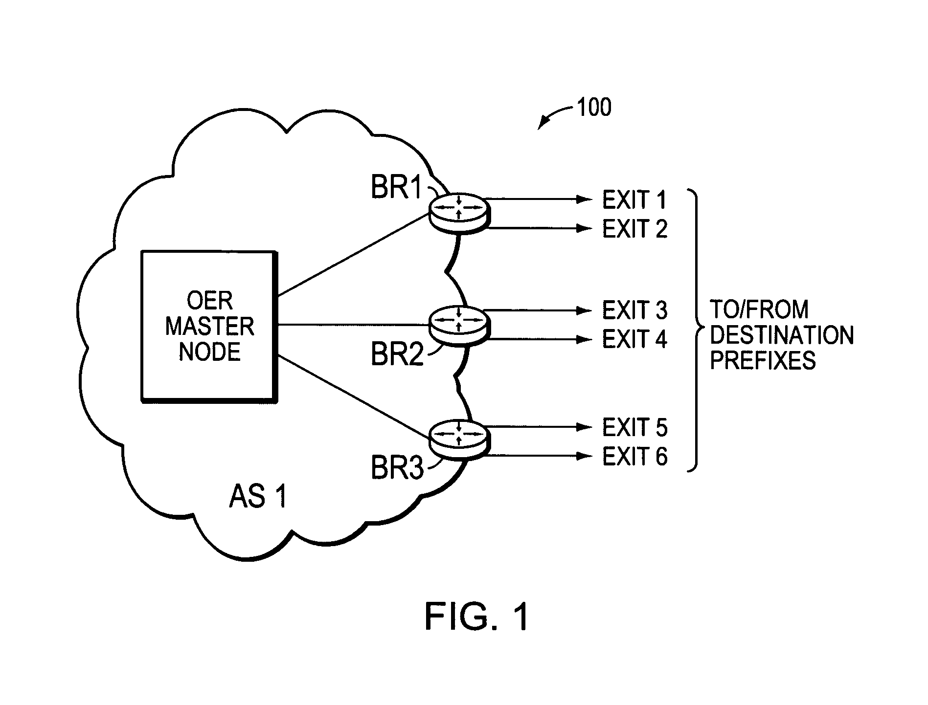
[0029]FIG. 1 is a schematic block diagram of an exemplary computer network 100 comprising an autonomous system (AS) AS1 (e.g., an enterprise or content provider network) interconnected to one or more destination prefixes (e.g., within one or more content consumer networks). Although AS1 is illustratively an autonomous system, those skilled in the art will appreciate that AS1 may be configured as one or more routing domains or other networks or subnetworks. AS1 comprises one or more network nodes, including a set of communicating border nodes (illustratively, edge or border routers, BRs) BR1, BR2, and BR3, through which client communications, such as data packet traffic, can pass into and out of the AS. For example, BR1-BR3 permit communication from AS1 to / from destination prefixes (e.g., via a wide area network, or WAN), such as through illustrative exits 1 and 2 on BR1, exits 3 and 4 on BR2, and exits 5 and 6 on BR3. Routing operations at the border nodes BR1-3 may be managed by an...


PUM


Abstract

A technique manages route optimization for one or more groups of links in a computer network. According to the novel technique, each group or “subgroup” of links comprises one or more links, wherein the group may be configured based on various measures, such as, e.g., connectivity (physical or virtual), policies to be applied, per-prefix, per-application (e.g., Internet traffic or voice over IP, VoIP), geographic location, and / or quality-based (e.g., primary links and secondary / backup links). One or more policies may be defined for the groups of links (i.e., where these group policies are to be applied to the group as a whole), in addition to policies that may be defined for individual to links and / or prefixes. Once the link groups are established, traffic over the groups of links (e.g., routes to reachable address prefixes) may be managed and optimized according to the group policies, such as in accordance with Optimized Edge Routing (OER) techniques.

Description

CROSS-REFERENCE TO RELATED APPLICATION[0001]The present application is related to commonly-owned copending U.S. patent application Ser. No. 11 / 336,584, entitled ROUTE OPTIMIZATION OF SERVICES PROVIDED BY ONE OR MORE SERVICE PROVIDERS FOR COMBINED LINKS, filed by Shah et al. on Jan. 20, 2006, the contents of which are hereby incorporated in its entirety.BACKGROUND OF THE INVENTION[0002]1. Field of the Invention[0003]The present invention relates to computer networks and more particularly to the management of links in a computer network.[0004]2. Background Information[0005]A computer network is a geographically distributed collection of nodes interconnected by communication links and segments for transporting data between end nodes, is such as personal computers and workstations (“hosts”). Many types of networks are available, with the types ranging from local area networks (LANs) to wide area networks (WANs). LANs typically connect the nodes over dedicated private communications link...

Claims


Application Information

Patent Timeline
IPC IPC(8): G06F15/173G08C15/00G01R31/08H04J1/16H04L12/26H04L29/06
CPCH04L29/06H04L69/14Y02D30/50H04L9/40
Inventor SHAH, PRITAM
Owner CISCO TECH INC
Learn More