Method for manufacturing a medical tube

a manufacturing method and flexible technology, applied in the direction of tubular articles, catheters, other domestic objects, etc., can solve the problems of difficult to ensure, inferior tensile strength of thin-walled tubes, kink resistance of thin-walled tubes, etc., and achieve excellent kink resistance and tensile strength. , the effect of simple manufacturing method

Active Publication Date: 2015-04-21
KANEKA CORP
View PDF9 Cites 0 Cited by
  • Summary
  • Abstract
  • Description
  • Claims
  • Application Information

AI Technical Summary

Benefits of technology

[0032]As described above, the present invention enables the stable supply of a thin-walled flexible medical tube having excellent kink resistance and tensile strength by the simple manufacturing method. As a result, the obtained medical tube can be effectively used as a component of a medical device such as various catheters.

Problems solved by technology

Until now, it has been very difficult to ensure that such a thin-walled tube has kink resistance of preventing a catheter from being bent even at a bent part or a curved part of a blood vessel, inner cavity retention performance when a catheter is highly bent, and tensile strength for preventing a catheter from being easily broken when, for example, the catheter is caught in the body.
The coil structure is extremely excellent in the kink resistance and the inner cavity retention performance when a tube is highly bent but is inferior in the tensile strength.
However, a heavy-walled tube has an increased outer diameter or a reduced inner diameter, and this raises problems in which, for example, such a tube cannot be inserted into a thinner peripheral blood vessel, cannot achieve a minimally invasive treatment, and causes the reduction of the injection performance, the aspiration performance, and the delivery performance.
A tube including a resin having high rigidity generally has low toughness, and this raises problems in which the resin layer cracks when the tube is highly bent, thereby reducing the kink resistance and the tensile strength.
Hence, such a tube cannot be safely used.
Though the method surely suppresses the elongation in the axial direction, the strength of a wire of the axial member is required to be increased against a higher tensile force, and a catheter obtained by the method may cause anisotropic flexural rigidity.
Therefore, such a tube is difficult to be applied to the leading end of a catheter that is required to have flexibility and high tensile force.
These techniques have structures requiring a reinforcement layer in addition to the coil layer and the resin layer and hence are absolutely impossible to be applied to a thin-walled tube.

Method used

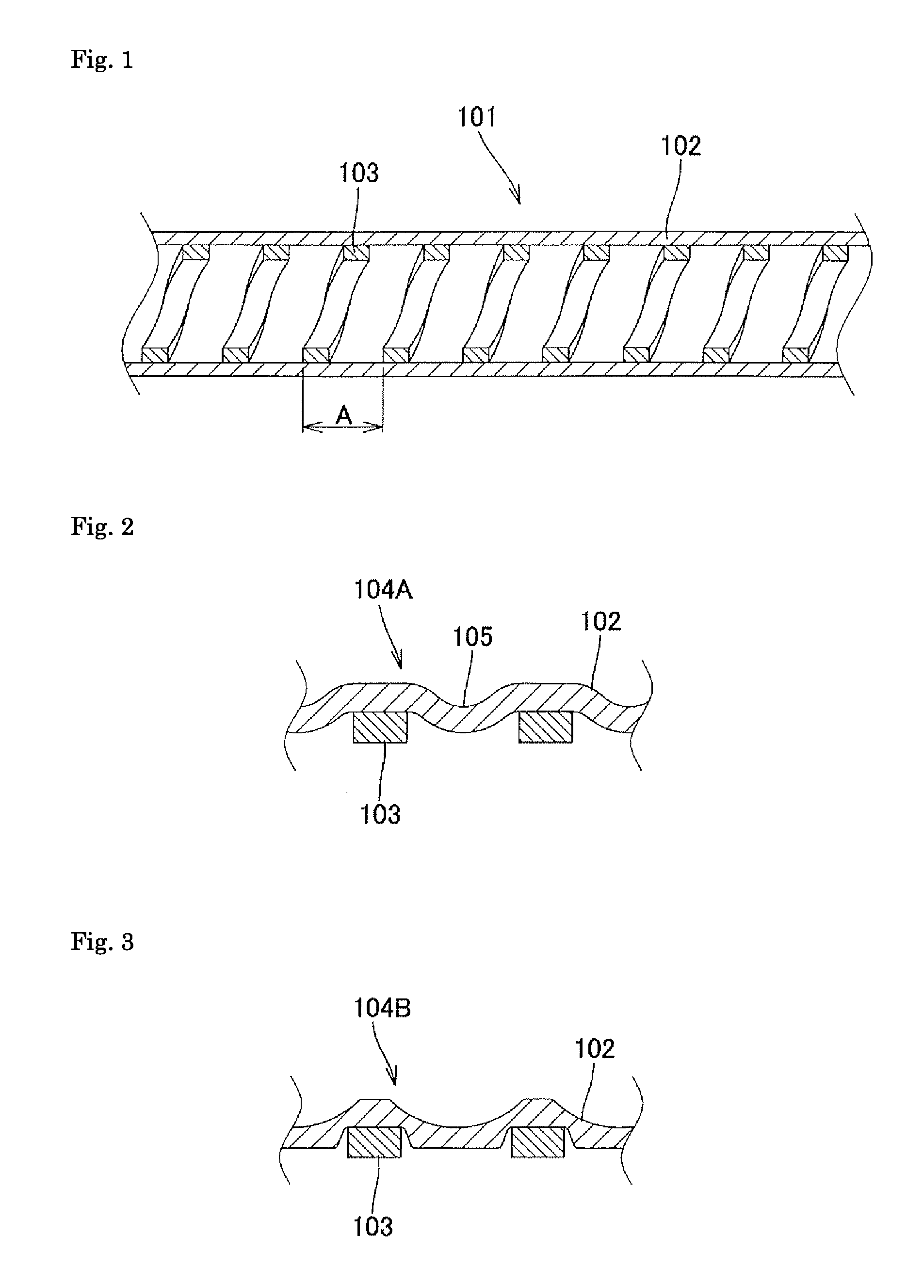
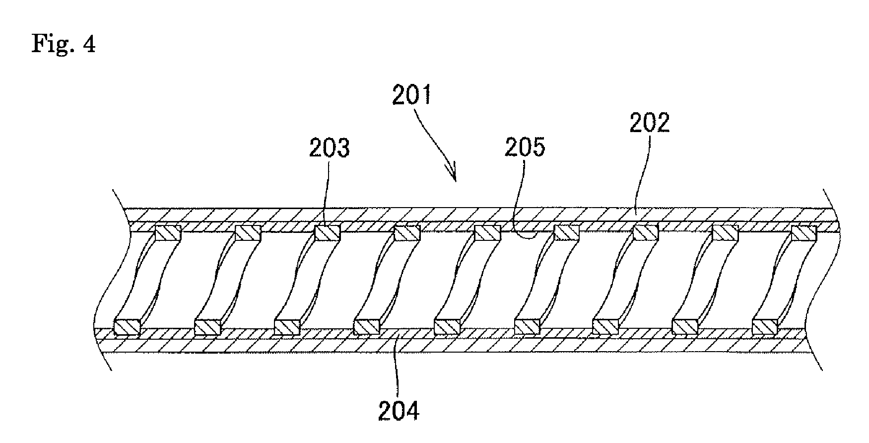

Image

  • Method for manufacturing a medical tube
  • Method for manufacturing a medical tube
  • Method for manufacturing a medical tube

Examples


example 1

[0125]A coil layer used was a tightly wound coil having an inner diameter of 1.00 mm and a length of 300 mm and made of a stainless steel flat wire (a thickness of 0.10 mm, a width of 0.20 mm). An outer layer tube used was a polyurethane elastomer (a Shore D hardness of 68 D, a melting point of 182° C.) tube that had an inner diameter of 1.25 mm and an outer diameter of 1.39 mm and was prepared using an extruder through extrusion molding by common pulling down while injecting air into an inner cavity.

[0126]Into the inner cavity of the prepared coil, a stainless steel core material having a diameter of 0.98 mm and a length of 400 mm was inserted, and the whole was inserted into the outer layer tube. The whole in this state was heated in an oven adjusted at 130° C. for 2 minutes. After taking out from the oven, the stainless steel core material was pulled out, thereby affording a medical tube having an inner diameter of 1.00 mm, an outer diameter of 1.35 mm, and a length of 300 mm.

example 2

[0127]A coil layer used was a pitch wound coil having an inner diameter of 1.00 mm, a clearance between wires of 0.05 mm (a pitch of 0.15 mm), and a length of 300 mm and made of a stainless steel flat wire (a thickness of 0.02 mm, a width 0.10 mm). An outer layer tube and an intermediate layer used were a two-layer tube that had an inner diameter of 1.08 mm, an outer diameter of 1.20 mm, and a length of 300 mm, included an outer layer (outer layer tube) having a thickness of 0.05 mm and made of a polyurethane elastomer (a Shore D hardness of 68 D, a melting point of 182° C.) and an inner layer (intermediate layer) having a thickness of 0.01 mm and made of a polyurethane elastomer (a Shore A hardness of 85 A, a melting point of 163° C.), and was prepared using an extruder through extrusion molding of two-layer tube by common pulling down while injecting air into an inner cavity.

[0128]Into the inner cavity of the prepared coil, a stainless steel core material having a diameter of 0.98...

example 3

[0129]A coil layer was the same as in Example 1. An outer layer tube used was a polyamide elastomer (a Shore D hardness of 72 D, a melting point of 176° C., a heat deformation temperature of 106° C.) tube that had an inner diameter of 1.25 mm and an outer diameter of 1.39 mm and was prepared using an extruder through extrusion molding by common pulling down while injecting air into an inner cavity.

[0130]Into the inner cavity of the prepared coil, a stainless steel core material having a diameter of 0.98 mm and a length of 400 mm was inserted, and the whole was inserted into the outer layer tube. The whole in this state was heated in an oven adjusted at 130° C. for 2 minutes. After taking out from the oven, the stainless steel core material was pulled out, thereby affording a medical tube having an inner diameter of 1.00 mm, an outer diameter of 1.35 mm, and a length of 300 mm.


PUM

PropertyMeasurementUnit
inner diameter shrinkage ratioaaaaaaaaaa
shrinkage ratioaaaaaaaaaa

Abstract

It is an object to stably provide a thin-walled flexible medical tube having excellent kink resistance and tensile strength by a simple manufacturing method. The object is achieved by a method for manufacturing a medical tube that includes a coil layer on an inside of an outer layer tube made of a resin, and the method includes inserting the coil layer into the outer layer tube and heating the outer layer tube at a molding temperature lower than a melting point of the outer layer tube, thereby bringing the outer layer tube into contact with the coil layer to slidably fix the outer layer tube onto the coil layer.

Description

TECHNICAL FIELD[0001]The present invention relates to a thin-walled flexible medical tube having excellent kink resistance and tensile strength and a method for manufacturing the medical tube.BACKGROUND ART[0002]There is a conventionally carried out medical practice in which a catheter is percutaneously inserted into a blood vessel and is introduced to an organ such as the brain, the heart, and the abdomen, thereby administrating and injecting, for example, a therapeutic agent, an embolic material, or a contrast medium, delivering, for example, an endoscope, another catheter, or a guide wire, or aspirating, for example, a blood clot. With the recent progress in medicine, for example, the treatment in a thinner peripheral blood vessel and a minimally invasive treatment using a catheter having a smaller outer diameter have been being carried out, and such a treatment requires a catheter having a smaller diameter but having higher performance than ever before. Examples of the performan...

Claims


Application Information

Patent Timeline
Patent Type & Authority Patents(United States)
IPC IPC(8): B29C65/00A61M25/00
CPCA61M25/0012A61M25/0009A61M25/005
Inventor TAHARA, HITOSHISAKATA, AKITOSHI
Owner KANEKA CORP
Why Eureka
Try Eureka