
Module for transferring a component between two positions

a technology of components and modules, applied in the field of modules for transferring components, can solve the problems of comparatively complex construction of modules, inability to adjust, and general consideration of hydraulics in glass molding machines, etc., and achieve the effect of simple design and simple adjustmen

Inactive Publication Date: 2015-04-21
HEYE INT
View PDF13 Cites 2 Cited by
  • Summary
  • Abstract
  • Description
  • Claims
  • Application Information

AI Technical Summary

Benefits of technology

The invention provides a device for transferring components, such as blow heads, along a transfer curve in a vertical plane. The device has a simple design and offers easy adjustment capabilities. A third carriage can be added to support the spring that describes the pre-tension, which makes it simple to adjust the position of the lower carriage and set the pre-tension as needed. Overall, the device is robust and efficient for transferring components in a vertical plane.

Problems solved by technology

The technical problem addressed in this patent is the need for a module that can transfer a component, such as a blow head, a baffle, or a funnel, between two positions on an I. S. glass molding machine along a transfer curve, while being suitable for the harsh atmosphere of a glass factory and being able to handle the high transfer speed without the risk of falling over or damage of the hollow glass articles. The module should be simple in construction and should not require the use of hydraulics.

Method used


Image

  • Module for transferring a component between two positions
  • Module for transferring a component between two positions
  • Module for transferring a component between two positions

Examples


Embodiment Construction

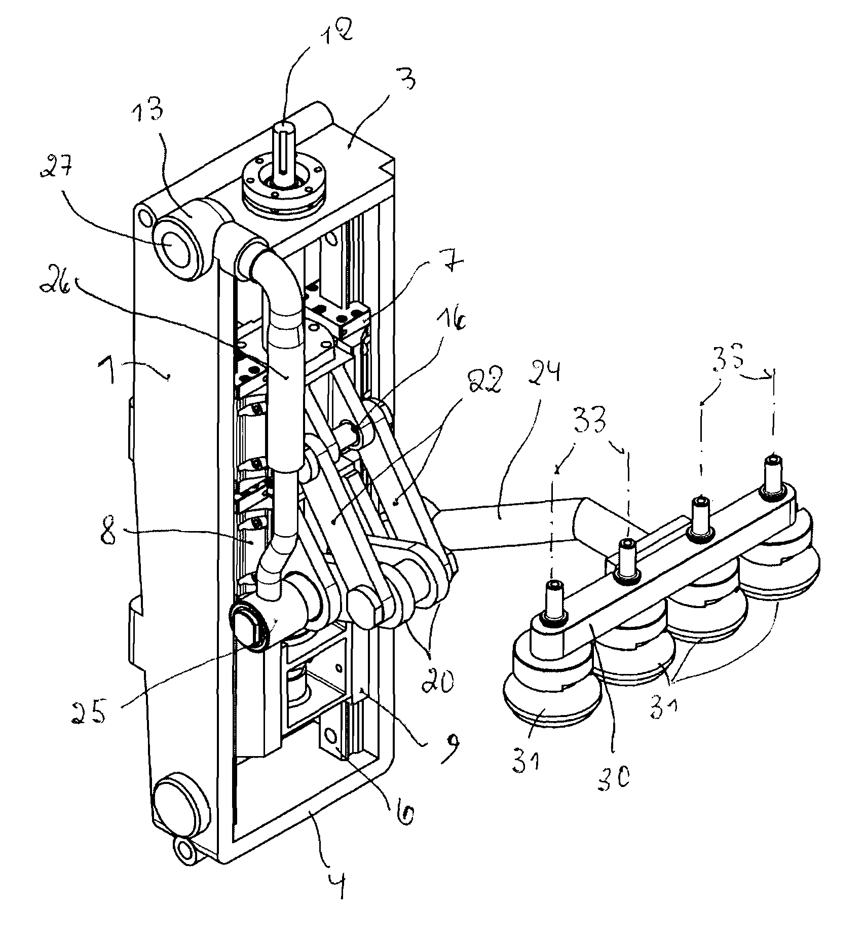
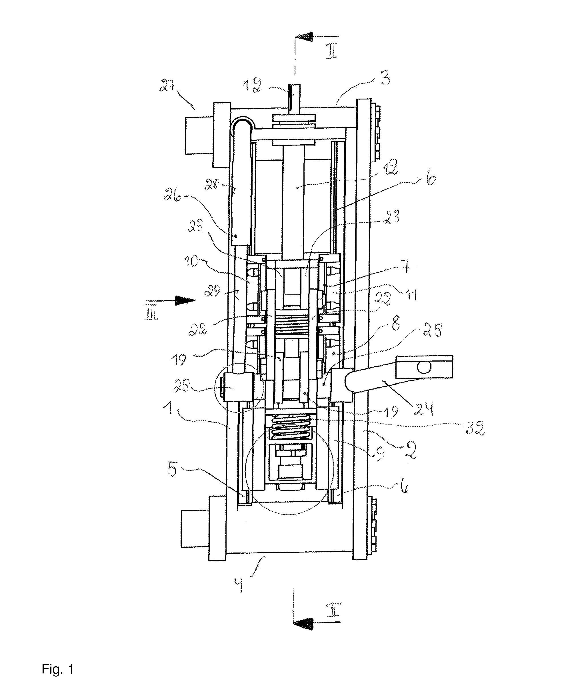
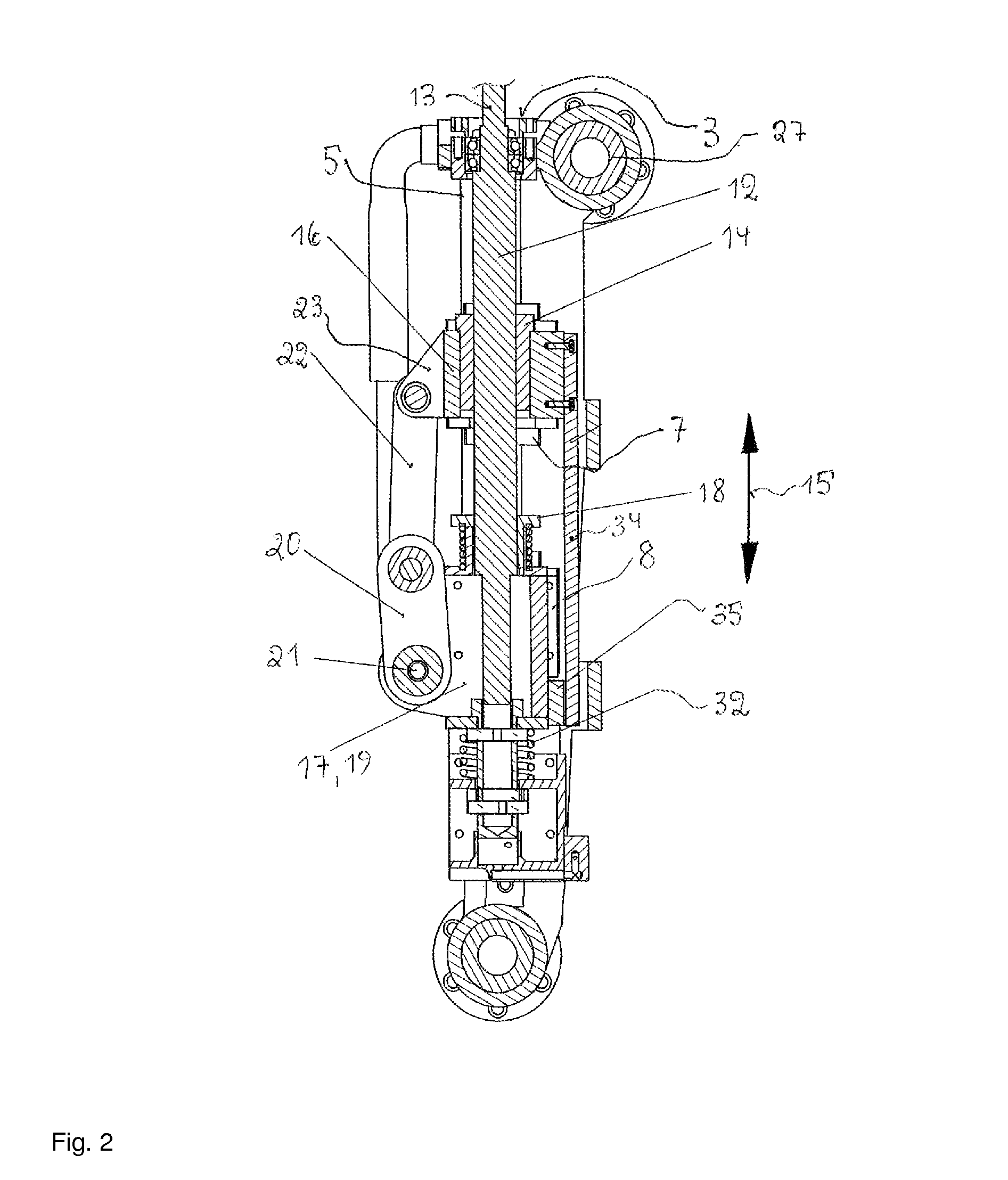
[0030]The module, which is conceived as a lift-pivot unit, is characterized by a framework consisting of two side walls 1, 2 extending vertically and parallel to one another, which form a closed frame in conjunction with top and bottom transverse walls 3, 4. Guides 5, 6, which are used as the carriers of a first carriage 7, a second carriage 8, and a third carriage 9, are located in each case on the sides of the side walls 1, 2 facing toward one another. Each carriage 7, 8, 9 is characterized by guide profiles 10, 11, which have a formfitting engagement with the guides 5, 6.

[0031]A threaded spindle is identified by 12 in FIG. 2, one end 13 of which protrudes out of the upper transverse wall 3 and has a drive connection at this point to a servomotor (not shown in the drawing). The threaded spindle 12 extends centrally between the side walls 1, 2, parallel thereto, and is engaged with a spindle nut 14 mounted in the first and uppermost carriage 7, so that by rotating the threaded spin...


PUM

PropertyMeasurementUnit
Forceaaaaaaaaaa
Areaaaaaaaaaaa

Abstract

A module for transferring a component of an I. S. glass molding machine, such as a blow head, between a first position and a second position along a transfer curve. The transfer curve includes a first partial movement consisting of a pivot movement around a horizontally extending axis and a second partial movement consisting of a vertically oriented linear movement in which the blow head is moved to its active position, resting to form a seal on the mouth area of a mold.

Description


Claims


Application Information

Patent Timeline
Owner HEYE INT
Learn More