
Covered rain gutter assembly

a rain gutter and assembly technology, applied in the field of rain gutters, can solve the problems of unwelcome and tedious manual removal of leaves, twigs, debris, and debris, and avoid the danger of collecting debris manually

Inactive Publication Date: 2015-04-07
GS CROWNLINE SERIES
View PDF31 Cites 19 Cited by
  • Summary
  • Abstract
  • Description
  • Claims
  • Application Information

AI Technical Summary

Benefits of technology

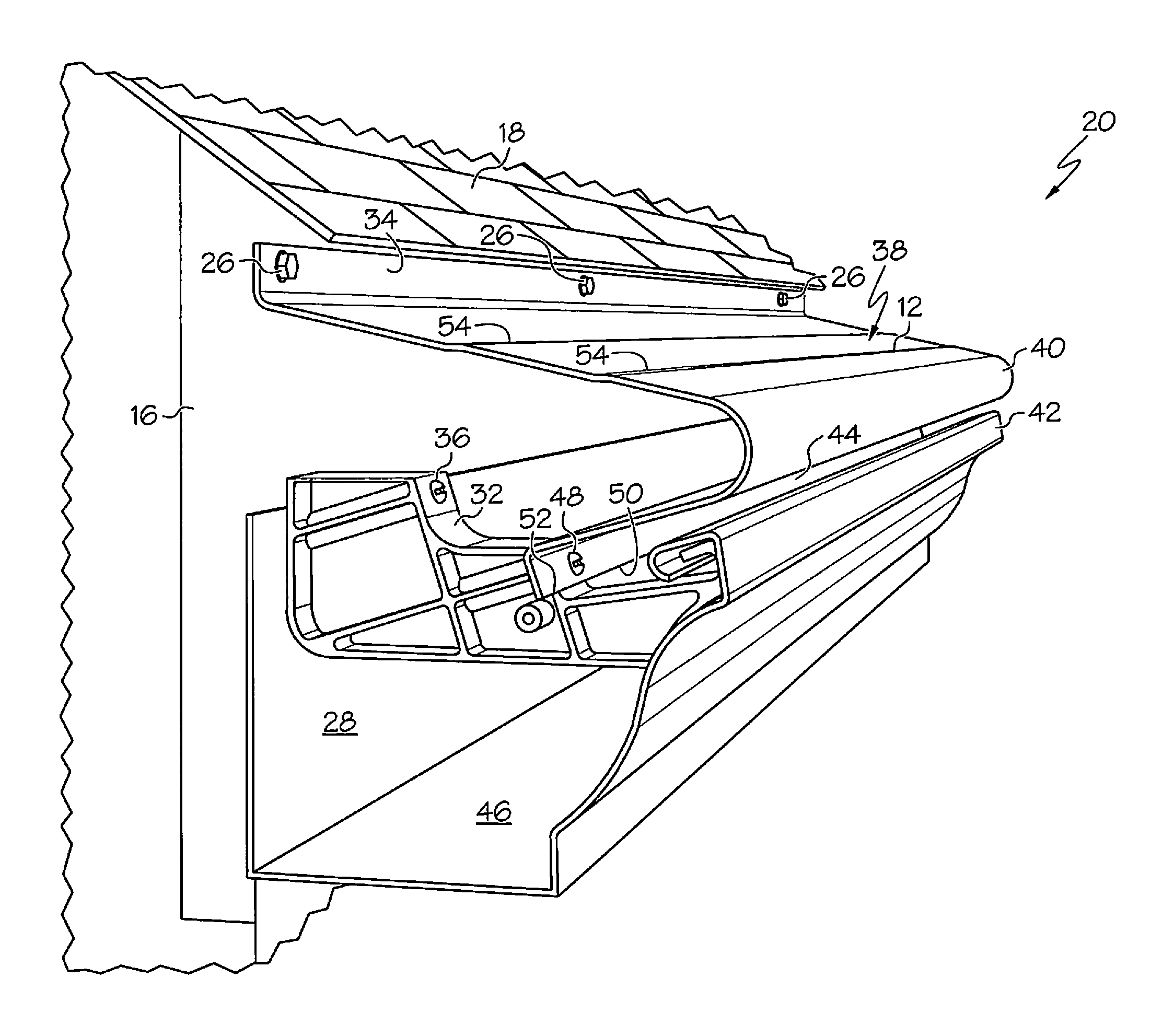
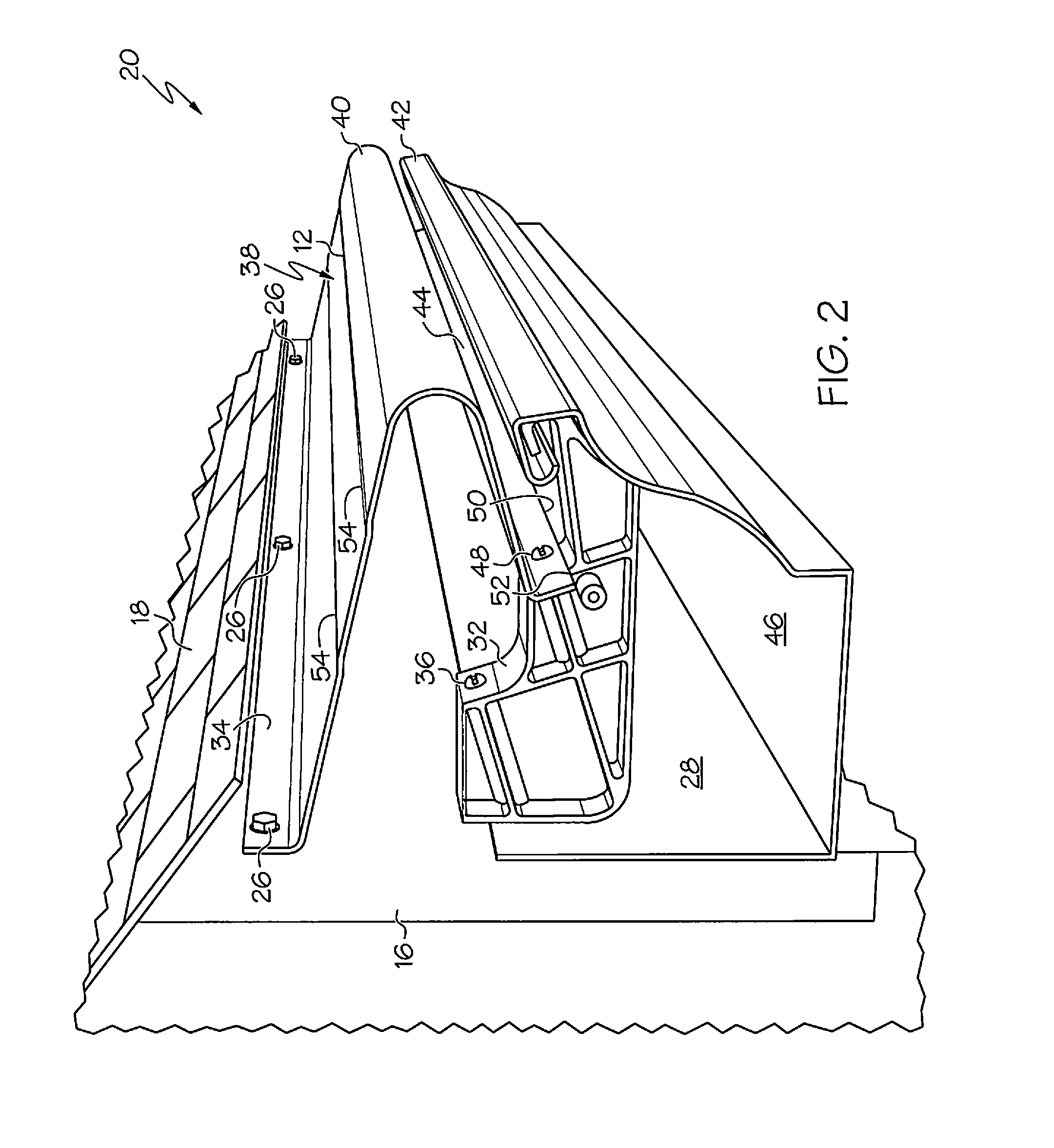
The present invention relates to a rain gutter assembly that includes a U-shaped gutter trough and support brackets for connecting the trough to a building surface. A cover is also provided to capture roof runoff. The technical effects of this invention include preventing clogging of the gutter by leaves and debris, and improved performance in directing roof runoff away from the building. Additionally, a support channel is provided for supporting the rain gutter cover in overlying relationship with the gutter trough, and a support bracket is utilized for the gutter trough end cap.

Problems solved by technology

The collected leaves, twigs, and other debris within an open gutter ultimately are carried by the roof runoff to a downspout opening in the is gutter trough, which ultimately leads to clogging of the gutter downspout opening, thereby causing filling of the gutter trough with roof runoff and resulting undesired gutter overflow onto the adjacent building wall.
The manual removal of collected leaves, twigs, and debris is an unwelcome and tedious chore—one that is potentially dangerous because it involves climbing a ladder to the building roof line in order to access the upwardly-facing opening of the gutter trough to enable removal of the collected leaves, twigs, and debris, and whatever other material that may be blocking the downspout opening in the gutter trough.
The danger attendant with manual removal of the collected debris arises from the possibility of falls from the ladder if the person doing the debris removal is not careful.
However, many such screening arrangements have the screening element positioned horizontally over the upwardly-facing gutter opening, or at a very slight inclination, thereby allowing a collection of leaves, twigs, and debris on the surface of the screening element, leading to external clogging or blocking of the upwardly-facing gutter trough opening rather than internal gutter trough clogging at a downspout opening.
As a result, the retained leaves can serve to partially block the upwardly-facing gutter opening and thus limit the flow of roof runoff into the gutter trough for collection.
Although several approaches to configuring and supporting a gutter cover in overlying relationship to an upwardly-facing gutter trough opening have been disclosed, those approaches are either cumbersome and time consuming from an installation standpoint, or they are costly in terms of amount of attachment materials needed, or they are not particularly rigid in terms of the rigidity of the overall gutter structure, or the security of its attachment to a building surface.

Method used


Image

  • Covered rain gutter assembly
  • Covered rain gutter assembly
  • Covered rain gutter assembly

Examples


Embodiment Construction

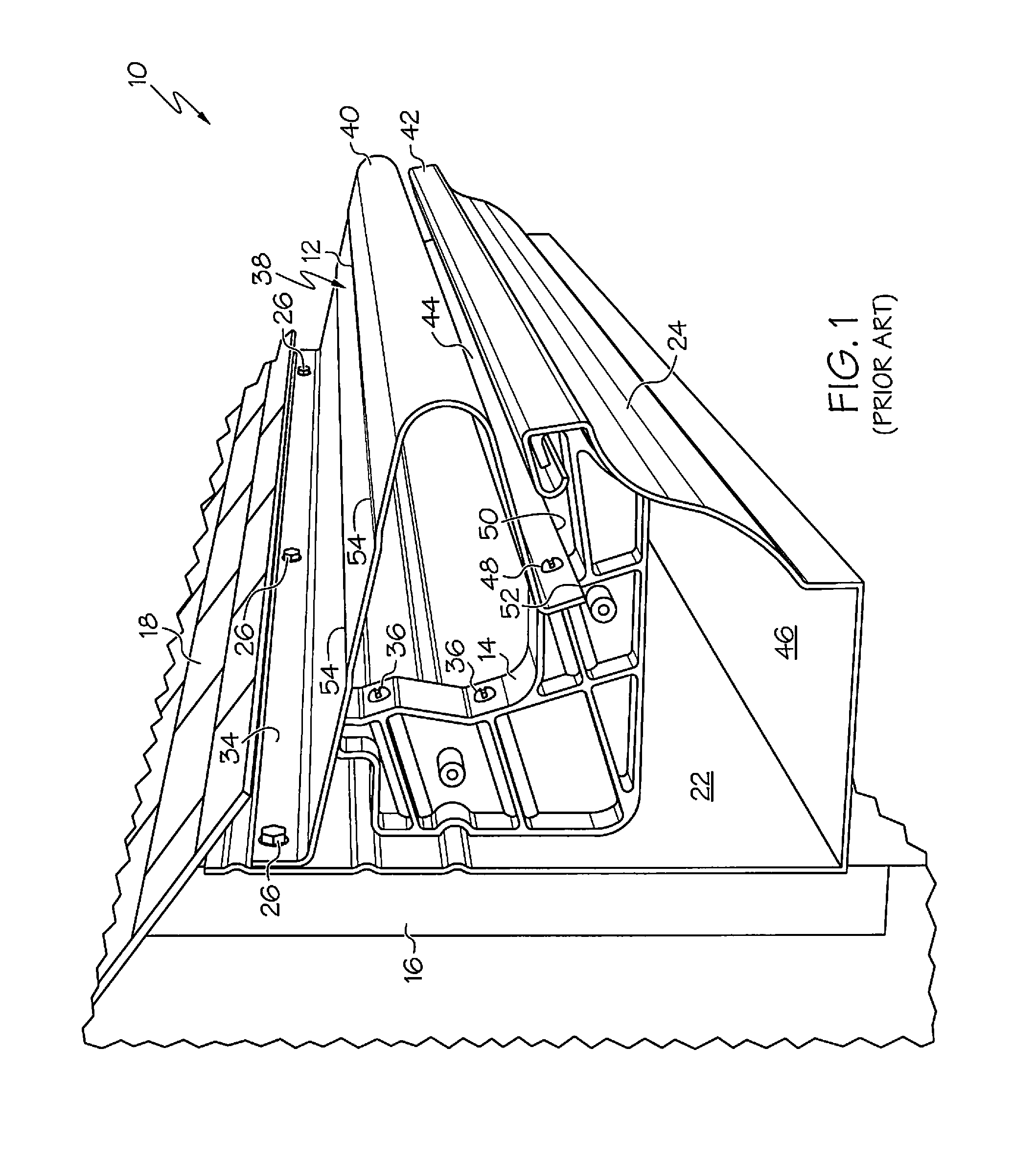
[0048]Referring to the drawings, and particularly to FIG. 1 thereof, there is shown an embodiment of a known rain gutter assembly including an imperforate cover that overlies the gutter trough upper opening to block the entry into the gutter trough of leaves, twigs, and debris that would otherwise block the downspout opening in the gutter trough. The structure and operation of that covered gutter embodiment is disclosed in U.S. Pat. No. 7,117,643 B2, which issued on Oct. 10, 2006, the entire contents of which is hereby incorporated herein by reference to the same extent as if fully rewritten. The gutter arrangement disclosed in that patent is a rain gutter assembly that includes a gutter trough 10, an imperforate gutter trough cover 12, and spaced support brackets 14 (only one of which is shown in FIG. 1) for supporting the cover in position over the upwardly-facing opening of the gutter trough. The several components of that assembly are interconnected with each other and provide a...


PUM


Abstract

A rain gutter assembly including an overlying cover. A gutter trough is in the form of a channel having an upwardly-facing opening. The cover overlies the channel opening and includes a front edge that is spaced from the front edge of the gutter channel to define a gap therebetween to allow roof runoff to flow around the convex front edge of the cover and into the channel. A series of longitudinally-spaced support brackets are positioned within the gutter channel and support the gutter trough and the cover to provide a rigid gutter assembly. An end cap is provided at each longitudinal end of the gutter channel and overlies both the gutter channel cross section and the space between the gutter channel cross section and the cover, to prevent entry of leaves, twigs, and debris into the channel through the ends of the gutter trough.

Description

CROSS-REFERENCE TO RELATED APPLICATIONS[0001]This application is a continuation-in-part of U.S. patent application Ser. No. 13 / 398,028, filed on Feb. 16, 2012, entitled “Rain Gutter Cover,” which claims priority from U.S. Provisional Patent Application Ser. No. 61 / 463,372, filed on Feb. 16, 2011, the entire contents of each of those applications is hereby incorporated by reference to the same extent as if fully rewritten.BACKGROUND OF THE INVENTION[0002]1. Field of the Invention[0003]The present invention relates to a covered rain gutter including a cover that is supported in overlying relationship with an upwardly-facing gutter trough opening. The cover serves to deflect leaves, twigs, and other debris and prevents them from entering the gutter trough and causing gutter clogging, while allowing free and unimpeded entry into the gutter trough of roof rainwater runoff. More particularly, the present invention relates to a covered rain gutter having a cover panel and having brackets t...

Claims


Application Information

Patent Timeline
Patent Type & Authority Patents(United States)
IPC IPC(8): E04D13/00E04D13/076F16M13/02
CPCE04D13/076F16M13/02
Inventor STEINBERG, MARK SLUCAS, STEVEN D
Owner GS CROWNLINE SERIES
Learn More