Eureka AIR delivers breakthrough ideas for toughest innovation challenges, trusted by R&D personnel around the world.

Systems and methods for initializing regions of a flash drive having diverse error correction coding (ECC) schemes

a flash drive and error correction technology, applied in the field of electronic devices, can solve the problems of affecting the signal-to-noise ratio of memory cells to change over time, so as to improve the performance of flash memory cells, flash memory, and low write amplification

Active Publication Date: 2015-03-31
IP GEM GRP LLC
View PDF108 Cites 23 Cited by
  • Summary
  • Abstract
  • Description
  • Claims
  • Application Information

AI Technical Summary

Benefits of technology

This patent describes techniques for improving the performance of flash memory in solid-state drives. The techniques include using a three-dimensional turbo code with primary and secondary error correction codes, reducing write amplification with a journaling filing system or flash translation layer, and selecting an error correction coding scheme based on the bit error rate of a region associated with a plurality of flash memory pages. These techniques can lead to lower uncorrectable bit error rates, longer life, faster and efficient retrieval, and efficient storage density, making it possible to implement enterprise storage applications using inexpensive MLC flash.

Problems solved by technology

Over time, programming and erasing flash memory causes a variety of defects that degrade the performance of the flash memory cell.
In particular, MLC memory cells have much lower program / erase cycle lifetimes than SLC memory cells, which can be a problem in an enterprise application.
This degradation, along with other noise effects, cause the signal-to-noise ratio of the memory cell to change over time.
After the signal-to-noise ratio has fallen to a certain level, the flash memory device is typically no longer reliable.
Taken together, these effects tend to cause the signal-to-noise ratio of flash memory to decrease with each passing generation.
For example, consumer grade flash-based drives may tolerate a relatively high uncorrectable error rate.
However, conventional approaches of applying ECC to flash memory can be inefficient at achieving relatively low uncorrectable error rates over the total service life and traffic loads that can be required in an enterprise storage environment, such as in a server.
If that fails, then ECC decoding has failed, and a read response is sent indicating that the user data was uncorrectable.

Method used


Image

  • Systems and methods for initializing regions of a flash drive having diverse error correction coding (ECC) schemes
  • Systems and methods for initializing regions of a flash drive having diverse error correction coding (ECC) schemes
  • Systems and methods for initializing regions of a flash drive having diverse error correction coding (ECC) schemes

Examples


Embodiment Construction

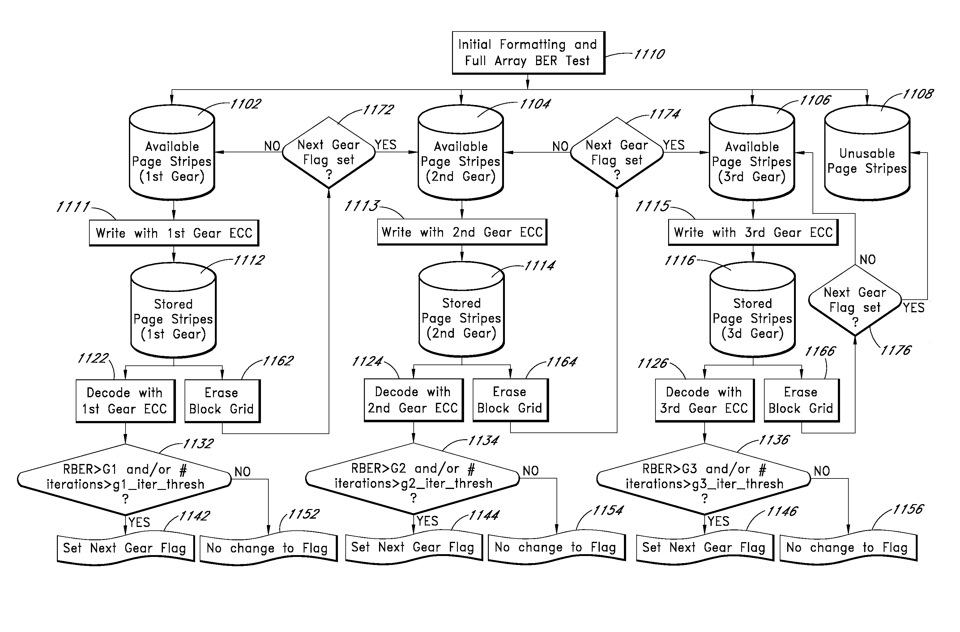
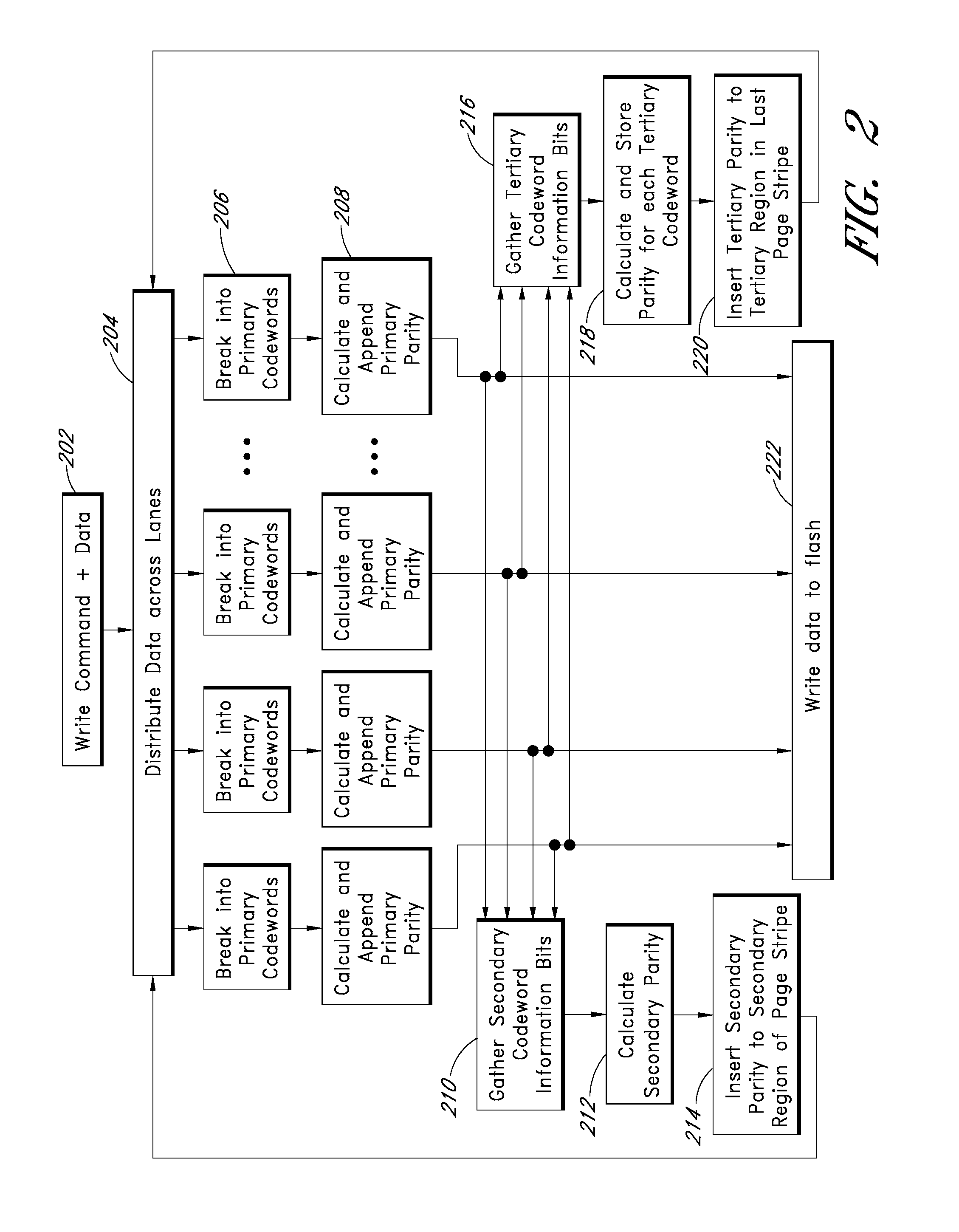
[0073]Although particular embodiments are described herein, other embodiments of the invention, including embodiments that do not provide all of the benefits and features set forth herein, will be apparent to those of ordinary skill in the art. For example, one embodiment of the invention corresponds to an SSD memory controller or a flash drive controller with one or more of the following features: (1) translation of logical or virtual addresses and real addresses via a journaling file system or flash translation layer to reduce the number of program / erase cycles to the memory cells (see FIG. 12); (2) selection of a strength of error correction coding based on a raw bit error rate (see FIG. 11); (3) provision of one or more additional error correction codes so that lower latency reads for small numbers of errors are possible as well additional error correction for larger numbers of errors (see FIGS. 8 and 9); and / or (4) rebuilding of an entire failed page from redundant data (see FI...


PUM


Abstract

Apparatus and methods provide relatively low uncorrectable bit error rates, low write amplification, long life, fast and efficient retrieval, and efficient storage density such that a solid-state drive (SSD) can be implemented using relatively inexpensive MLC Flash for an enterprise storage application.

Description

CROSS-REFERENCE TO RELATED APPLICATIONAppendix A[0001]Appendix A, which forms a part of this disclosure, is a list of commonly owned copending U.S. patent applications. Each one of the applications listed in Appendix A is hereby incorporated herein in its entirety by reference thereto.BACKGROUND[0002]1. Field of the Invention[0003]Embodiments of the invention generally relate to electronics, and in particular, to flash drive memory controllers, such as to solid-state drive memory controllers.[0004]2. Description of the Related Art[0005]Flash memory is a form of non-volatile memory. A memory cell in flash memory can be a single-level cell (SLC), which encodes one bit of information per cell, or a multi-level cell (MLC), which encodes two or more bits of information per memory cell. Typically, a flash memory implementation using MLC is much cheaper than a flash memory implementation with SLC. Further, a flash memory device is arranged into pages and blocks. Data can be written to and ...

Claims


Application Information

Patent Timeline
Patent Type & Authority Patents(United States)
IPC IPC(8): G06F11/00G06F11/10H03M13/35
CPCG06F11/1068G06F11/1008H03M13/35H03M13/1102H03M13/1515H03M13/152H03M13/2906H03M13/2927H03M13/2945H03M13/2963G06F11/1012G06F11/108
Inventor NORTHCOTT, PHILIP L.
Owner IP GEM GRP LLC
Why Eureka
Eureka Blog
Learn More