
Howling canceller

a canceller and howling technology, applied in the field of howling cancellers, can solve the problems of difficult to suppress howling by adaptive filters, non-linear distortion, and difficulty in detecting non-linear distortion, so as to prevent non-linear distortion, suppress howling, and prevent bias of adaptive systems

Inactive Publication Date: 2015-03-31
YUGENGAISYA CEPSTRUM
View PDF26 Cites 5 Cited by
  • Summary
  • Abstract
  • Description
  • Claims
  • Application Information

AI Technical Summary

Benefits of technology

The present invention introduces an amplitude limiting circuit in a feedback loop of a system to be identified. This circuit prevents the amplitude of an input signal from exceeding a predetermined threshold value, which ensures that all components of the system operate in a linear region without being saturated. This prevents non-linear distortion and avoids bias of the adaptive system. The occurrence of howling in the playback band is also suppressed, even if the open loop gain exceeds "1."

Problems solved by technology

However, if a change occurs in the transmission characteristics of the acoustic system between the microphone and the speaker, it is difficult to suppress the howling with the technology disclosed in Patent literature 1.
However, when a gain of a loudspeaker system exceeds “1” in a wide frequency range, convergence of the adaptive filter does not catch up the rapid growth of the amplitude of howling sound caused by positive feedback, the amplitude of the howling sound increases beyond the linear region of any one of a D / A converter, a power amplifier, a speaker, a microphone, a microphone amplifier, and an A / D converter, and the waveform of the howling sound is saturated, resulting in the occurrence of non-linear distortion.
Therefore, if howling occurs in the loudspeaker system with a gain exceeding “1” over a wide frequency range and reaches a saturation state once, it is difficult to suppress the howling by the adaptive filter.

Method used


Image

  • Howling canceller
  • Howling canceller
  • Howling canceller

Examples


embodiment 1

[0056](Embodiment 1)

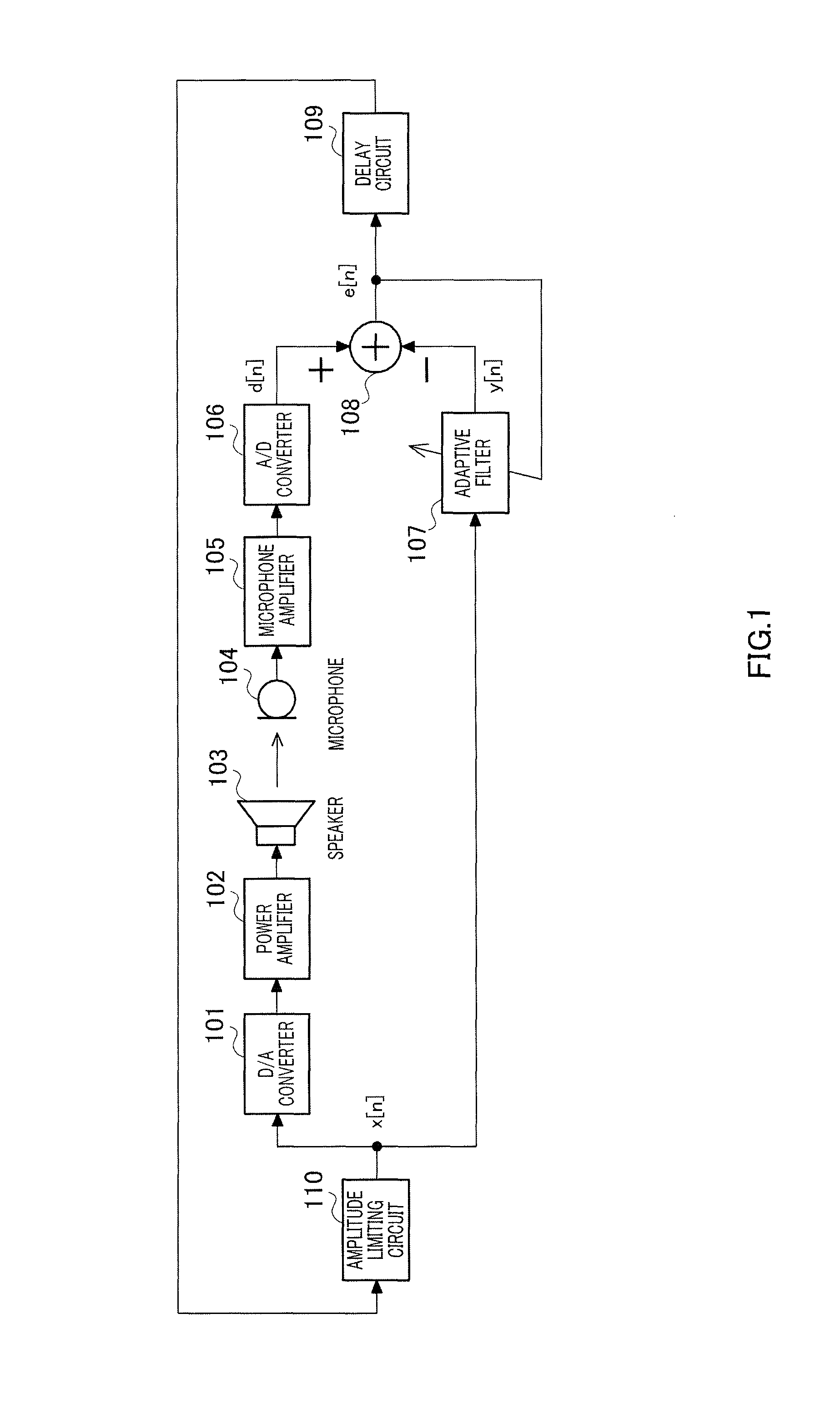
[0057]FIG. 1 is a block diagram showing a configuration of a loudspeaker according to Embodiment 1 of the present invention.

[0058]As shown in FIG. 1, the loudspeaker includes digital-to-analog (D / A) converter 101, power amplifier 102, speaker 103, microphone 104, microphone amplifier 105, analog-to-digital (A / D) converter 106, adaptive filter 107, subtractor 108, delay circuit 109, and amplitude limiting circuit 110.

[0059]D / A converter 101 converts a digital received speech signal x[n] at the discrete time n into an analog received speech signal. The analog received speech signal output from D / A converter 101 is amplified by power amplifier 102.

[0060]Speaker 103 plays back the analog received speech signal output from power amplifier 102 and outputs sound. The playback sound output from speaker 103 is input to microphone 104.

[0061]Microphone 104 converts sound including the playback sound output from speaker 103 into an analog transmitted speech signal. The analo...

embodiment 2

[0084](Embodiment 2)

[0085]In Embodiment 2, a method for setting threshold value k of amplitude limiting circuit 110 shown in FIG. 1 will be described.

[0086]FIG. 4 is a diagram showing in detail the characteristics of each element of the loudspeaker of FIG. 1. In addition, FIG. 4 shows a model in which each of power amplifier 102, speaker 103, the acoustic system between speaker 103 and microphone 104, microphone 104, and microphone amplifier 105 has flat frequency characteristics.

[0087]In the model of FIG. 4, each of D / A converter 101 with non-linearity, power amplifier 102, speaker 103, microphone 104, microphone amplifier 105, and A / D converter 106 connects a non-linear system NL to a linear system L.

[0088]The non-linear system NL has input / output characteristics shown in FIG. 5A. In a linear region where an absolute value of the amplitude of an input signal is equal to or smaller than threshold value k, a gain of the non-linear system NL is “1” and output of the non-linear system...

embodiment 3

[0138](Embodiment 3)

[0139]In Embodiment 3, a case of automatically setting threshold value k while operating the loudspeaker in the state in which howling has actually occurred will be described.

[0140]FIG. 12 is a block diagram showing a configuration of the loudspeaker having the howling canceller therein according to the present embodiment. FIG. 12 shows a configuration in which threshold value setting circuit 200 is further added to the configuration of FIG. 1. Amplitude limiting circuit 110 limits the amplitude of input signal x[n] to be equal to or smaller than threshold value k set by threshold value setting circuit 200.

[0141]Threshold value setting circuit 200 includes absolute value circuit 201, Low Pass Filter (LPF) 202, constant generation circuit 203, multiplier 204, magnitude comparator 205, clock generation circuit 206, constant generation circuit 207, multiplier 208, and register 209.

[0142]Absolute value circuit 201 full-wave rectifies input signal x[n]. Low Pass Filte...


PUM


Abstract

A howling canceller which suppresses occurrence of howling even when an open loop gain exceeds “1” in the whole reproduction band. In the howling canceller, an adaptive filter (107) operates a digital received voice signal with a tap coefficient to generate a pseudo echo; a subtractor (108) subtracts the pseudo echo from a digital transmitted voice signal to generate a residual signal; and an amplitude limiting circuit (110) limits the absolute value of the amplitude of the digital received voice signal to be equal to or smaller than a predetermined threshold which ensures that all of a D / A converter (101), a power amplifier (102), a speaker (103), a microphone (104), a microphone amplifier (105), and an A / D converter (106) operate in a linear operation area, and outputs the amplitude-limited digital received voice signal to the D / A converter (101) and the adaptive filter (107).

Description

CROSS-REFERENCE TO PRIOR FILED APPLICATIONS:[0001]This is a National Phase Application filed under 35 U.S.C. §371 as a national stage of International Application No. PCT / JP2010 / 002004, filed on Mar. 19, 2010, claiming the benefit from Japanese Application 2009-068683, filed on Mar. 19, 2009, and claiming the benefit from Japanese Patent Application 2009-209298, filed on Sep. 10, 2009, the content of each of which is hereby incorporated by reference in its entirety.TECHNICAL FIELD[0002]The present invention relates to a howling canceller for suppressing howling of a speech signal using an adaptive filter.BACKGROUND ART[0003]Conventionally, there has been disclosed various howling cancellers capable of suppressing howling of a speech signal input from a microphone and emitting the resultant through a speaker and so forth.[0004]A conventional howling canceller based on analog processing without using an adaptive filter has been disclosed in Patent literature 1. Patent literature 1 dis...

Claims


Application Information

Patent Timeline
Patent Type & Authority Patents(United States)
IPC IPC(8): G10L21/00G10L21/02G10L21/0208H04R3/02H04R27/00
CPCH04R3/02G10L21/0208H04R27/00
Inventor YAMAGUCHI, AKIO
Owner YUGENGAISYA CEPSTRUM
Learn More