
Method and apparatus for uplink power control in wireless communication system

a wireless communication system and power control technology, applied in power management, wireless commuication services, high-level techniques, etc., can solve the problems of corresponding transmission rate, small transmission gain, and inability to obtain transmission ra

Active Publication Date: 2015-03-24
SAMSUNG ELECTRONICS CO LTD
View PDF11 Cites 201 Cited by
  • Summary
  • Abstract
  • Description
  • Claims
  • Application Information

AI Technical Summary

Benefits of technology

The present invention provides a method and device for allowing cells to work together to control the power of their signals and reduce interference with each other. This allows for better data transmission and improved overall efficiency of the communications network.

Problems solved by technology

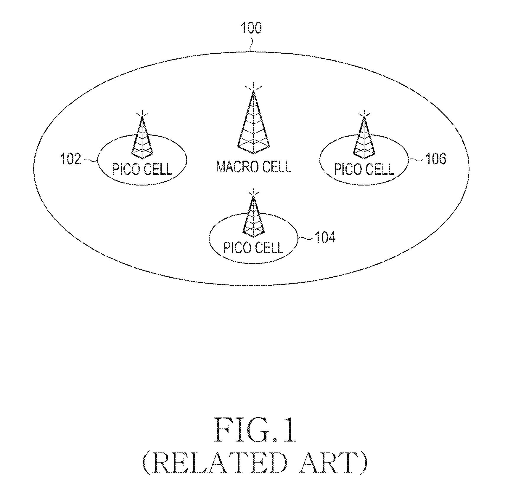
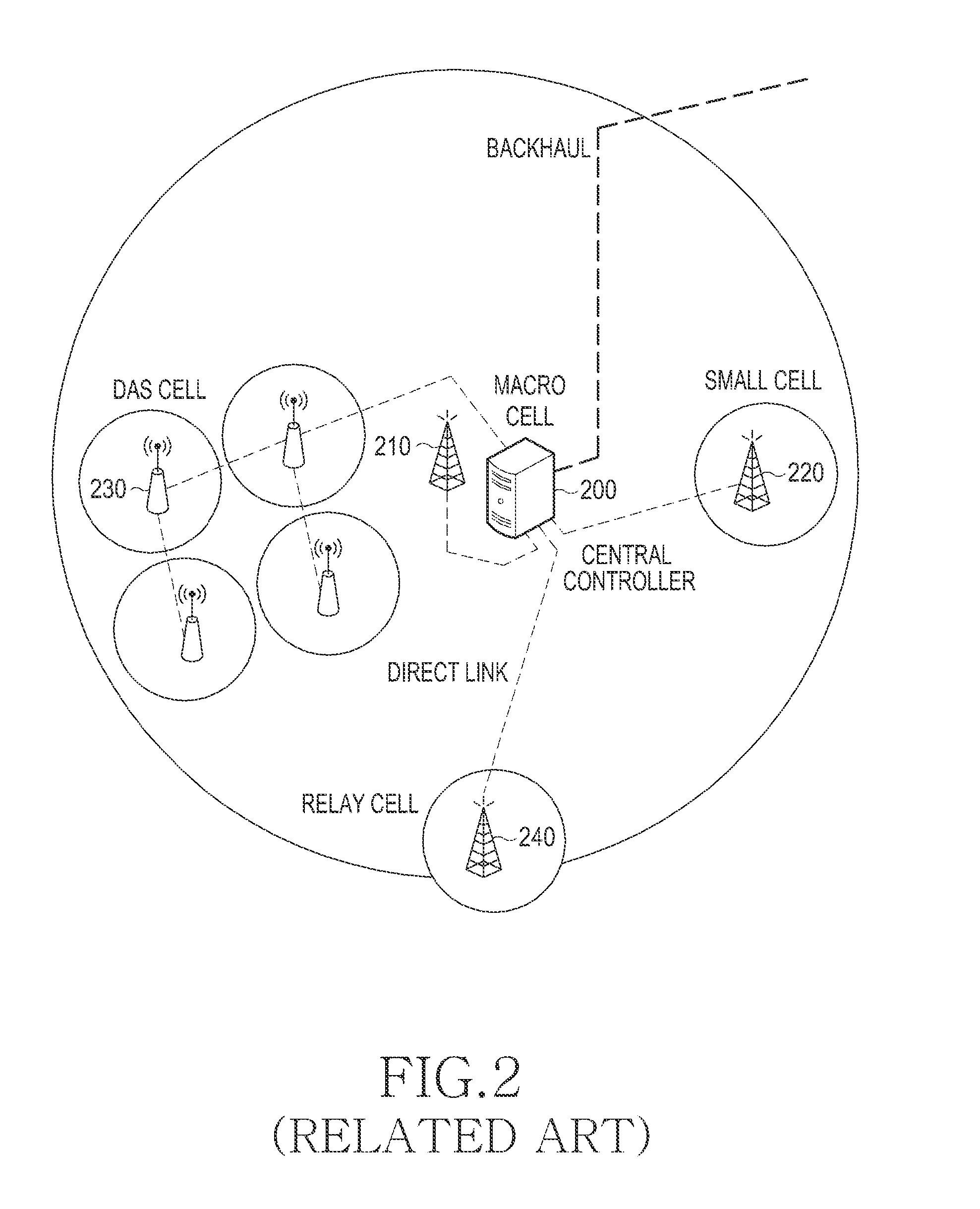
However, in the actual wireless communication environment, there is a problem in that even when N small cells are included in one macro cell, a transmission rate corresponding to N times of an existing transmission rate cannot be obtained and smaller transmission gain is achieved due to interference between heterogeneous cells and non-uniform distribution of mobile terminals.
That is, in a related heterogeneous network system, performance degradation may be caused by interference between a macro cell and a small cell, or by interference between small cells.
Also, in a related heterogeneous network system, non-uniform distribution of mobile terminals with respect to small cells may cause some resources to be unusable, thereby resulting in performance degradation of the related heterogeneous network system.
However, a method for controlling power using the above-mentioned centralized control scheme has not been concretely designed.
As a result, communication systems must use an existing inefficient power control method in the related network coordinate system employing a centralized control scheme, which results in performance degradation of the related network coordinate system.

Method used


Image

  • Method and apparatus for uplink power control in wireless communication system
  • Method and apparatus for uplink power control in wireless communication system
  • Method and apparatus for uplink power control in wireless communication system

Examples


Embodiment Construction

[0039]The following description with reference to the accompanying drawings is provided to assist in a comprehensive understanding of exemplary embodiments of the invention as defined by the claims and their equivalents. It includes various specific details to assist in that understanding but these are to be regarded as merely exemplary. Accordingly, those of ordinary skill in the art will recognize that various changes and modifications of the embodiments described herein can be made without departing from the scope and spirit of the invention. In addition, descriptions of well-known functions and constructions may be omitted for clarity and conciseness.

[0040]The terms and words used in the following description and claims are not limited to the bibliographical meanings, but, are merely used by the inventor to enable a clear and consistent understanding of the invention. Accordingly, it should be apparent to those skilled in the art that the following description of exemplary embod...


PUM


Abstract

A method and an apparatus for uplink power control in a wireless communication system are provided. More specially, a method is provided in which a first base station in a wireless communication system periodically measures interference for a cell of a second base station neighboring the first base station, determines an average of the periodically measured interference, broadcasts the determined average of the periodically measured interference to mobile terminals located in a cell of the first base station, determines a weight for the determined average of the periodically measured interference, based on one of resource allocation information for the cell of the second base station and whether a specific message for interference regulation is received from the second base station, and transmits the determined weight to the mobile terminals.

Description

PRIORITY[0001]This application claims the benefit under 35 U.S.C. §119(a) of a Korean patent application filed in the Korean Industrial Property Office on Feb. 16, 2011 and assigned Serial No. 10-2011-0013609, the entire disclosure of which is hereby incorporated by reference.BACKGROUND OF THE INVENTION[0002]1. Field of the Invention[0003]The present invention relates to a method and an apparatus for communicating in a wireless communication system. More particularly, the present invention relates to a method and apparatus for uplink power control in a wireless communication system.[0004]2. Description of the Related Art[0005]Recently, with the increasing demand for data communication and the continuing development of various communication services in a wireless communication system, there is an urgent need to increase transmission capacity. As a way to satisfy this need for an increase in transmission capacity, technology for heterogeneous networks is being actively studied. A hete...

Claims


Application Information

Patent Timeline
Patent Type & Authority Patents(United States)
IPC IPC(8): H04B7/00H04W16/32H04W52/02H04W52/24
CPCH04W52/244H04W52/0212H04W16/32Y02D30/70H04W52/146H04W72/20
Inventor JEONG, SU-RYONGPARK, JEONG-HOKIM, TAE-YOUNG
Owner SAMSUNG ELECTRONICS CO LTD
Learn More