
Autoretroperfusion devices and systems

a technology of autoretroperfusion and autoreplenia, which is applied in the field of autoreplenia devices and systems, can solve the problems of increasing the risk of having cad that is not effectively treated by conventional revascularization techniques, the percentage of patients diagnosed with symptomatic cad is not suitable for cabg or ptca, and the treatment effectiveness of conventional revascularization techniques is known to be ineffectiv

Active Publication Date: 2015-03-17
CVDEVICES
View PDF21 Cites 15 Cited by
  • Summary
  • Abstract
  • Description
  • Claims
  • Application Information

AI Technical Summary

Benefits of technology

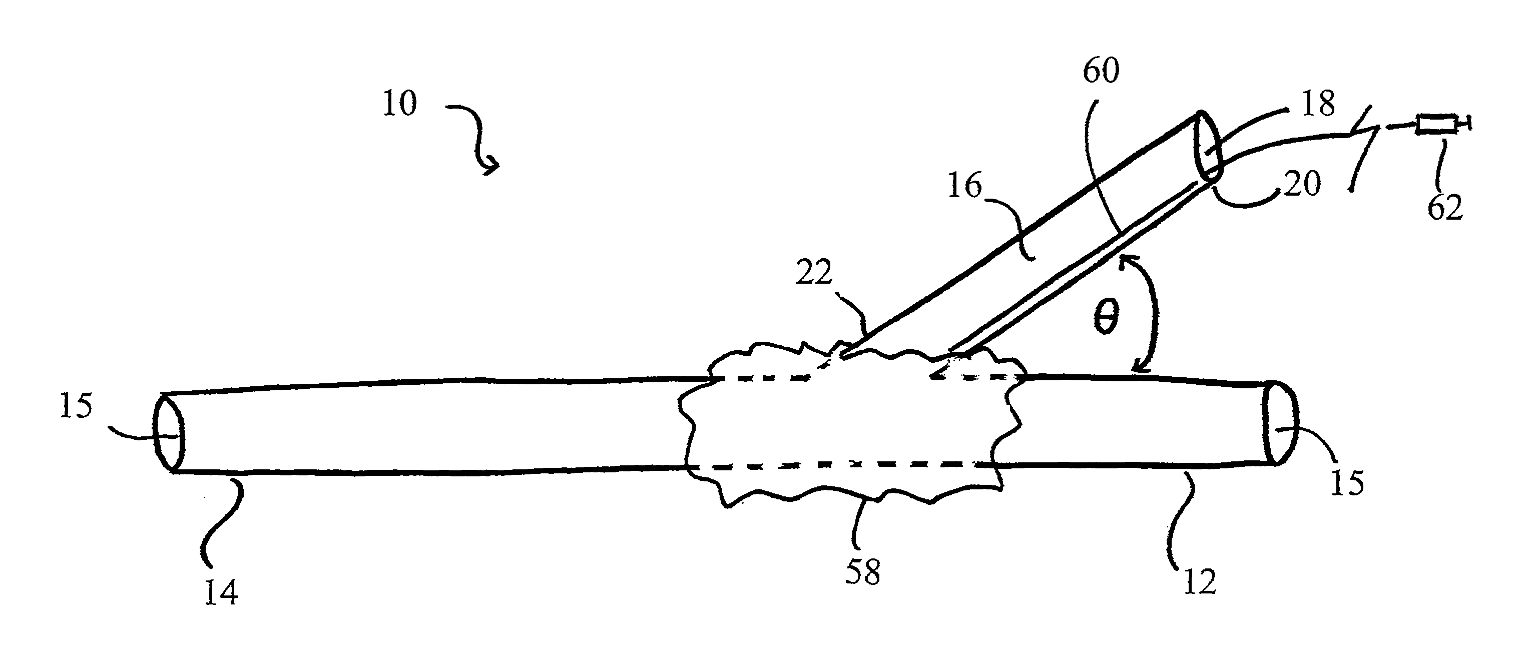
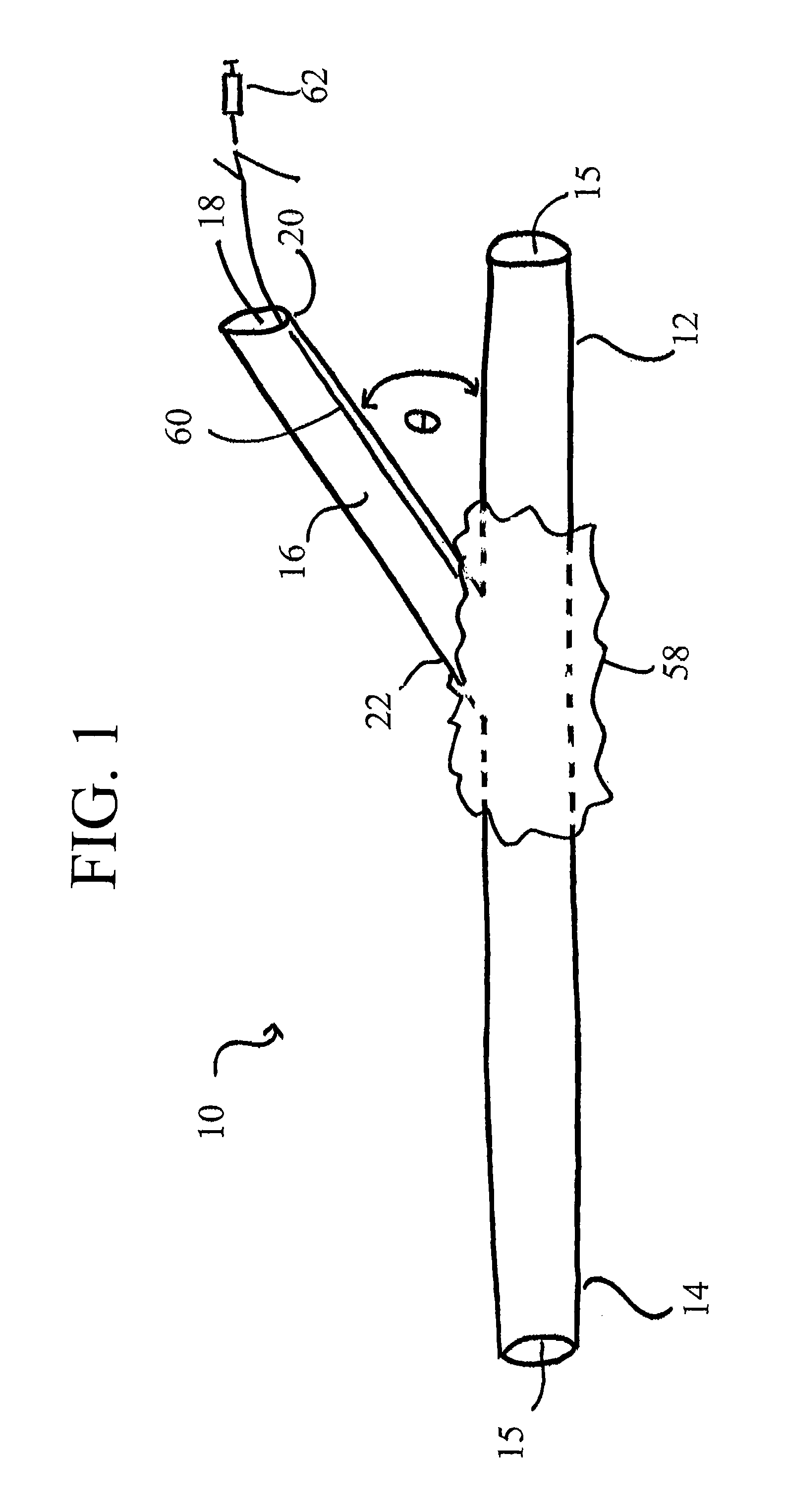
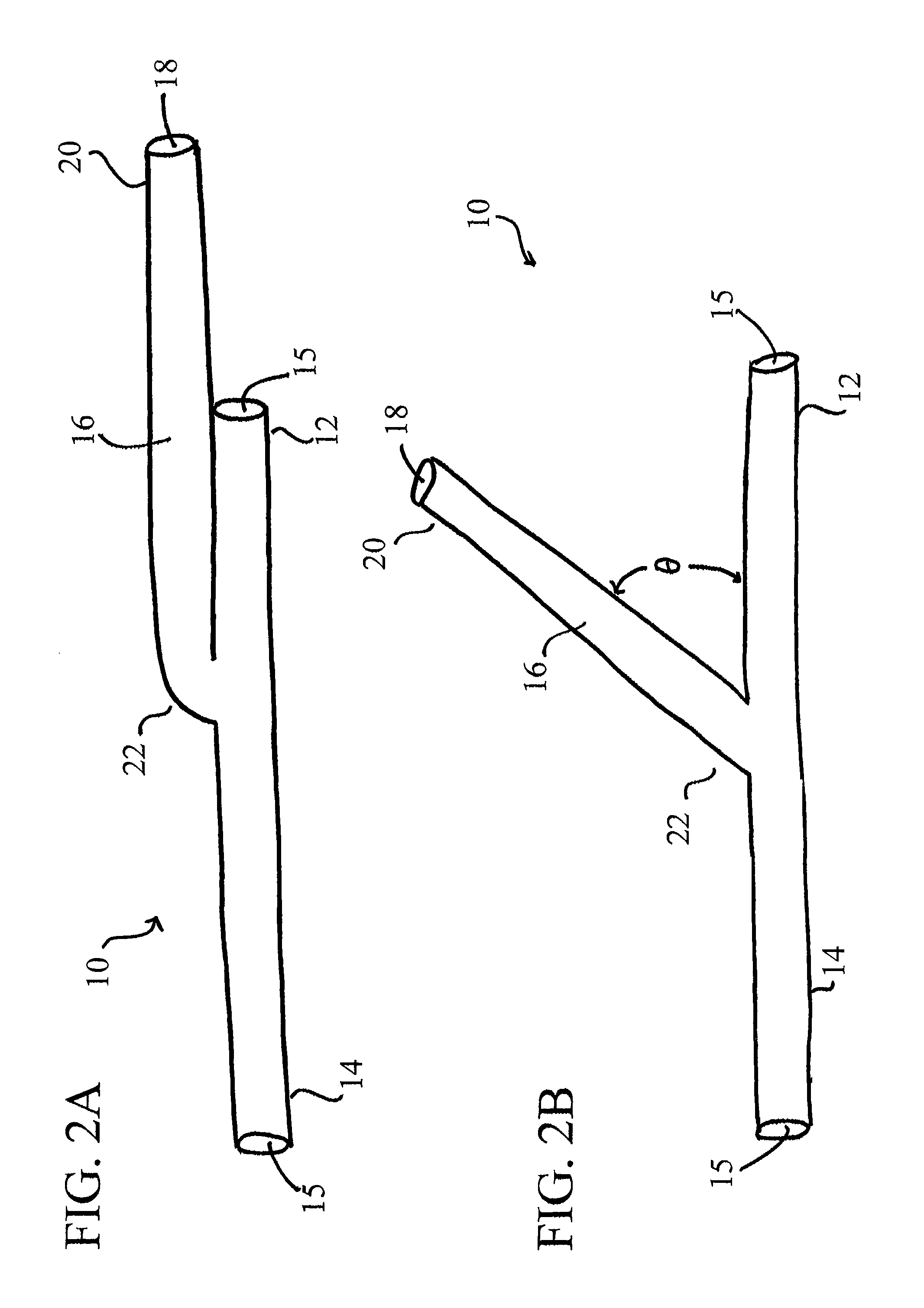
[0019]Disclosed herein are the devices, systems and methods for providing controlling blood perfusion pressure and / or providing retroperfusion to at least one ischemic tissue in a minimally invasive manner. At least some of the disclosed embodiments enable an anastomosis to be formed between a vein and an artery without the use of sutures and through a non-invasive procedure. In addition, various disclosed embodiments provide a cannula device comprising a Y-configuration for bifurcating the arterial flow between an anastomosis and the underlying artery. Examples of the devices, systems and methods described herein can further provide simultaneous autoretroperfusion therapy to more than one area of an ischemic tissue.
[0022]The catheter described herein may further comprise an expandable balloon coupled with the elongated body of the catheter in a position adjacent to where the cannula extends from the elongated body. The expandable balloon may comprise any configuration and, in at least one embodiment, is configured to prevent fluid leakage through an arterial opening when the expandable balloon is in a substantially inflated configuration and the elongated body of the catheter is positioned within an arterial vessel such that the cannula extends through the arterial opening. In this at least one embodiment, the catheter may also comprise a balloon port and a secondary lumen. Here, the balloon port may be in fluid communication with the expandable balloon through a secondary lumen of the catheter. The balloon port may be configured for subcutaneous implantation on a patient or otherwise.
[0027]In yet another at least one embodiment, the second catheter of the system may further comprise an expandable balloon coupled therewith. Where the system comprises a first expandable balloon coupled with the primary lumen of the second catheter and a second expandable balloon coupled with the second catheter, the first and second expandable balloons of the second catheter may be capable of being inflated and deflated independently of each other through respective balloon ports coupled therewith. Accordingly, a clinician can independently control each expandable balloon coupled with the second catheter.
[0033]In at least one method for arterializing a vein, the method comprises the steps of: providing the system described above; introducing the distal end of the first catheter into an artery through an arterial opening such that a first amount of arterial blood flows through the at least one lumen of the elongated body of the first catheter, the cannula extends through the arterial opening, and a second amount of arterial blood flows through the cannula of the first catheter; introducing the distal end of the second catheter into a vein to be arterialized; and forming an anastomosis between the artery and the vein by coupling the connector with the cannula of the first catheter and the proximal end of the second catheter. The method may also further comprise the step of decreasing the pressure of the amount of arterial blood flowing through the cannula of the first catheter prior to allowing the amount of arterial blood to flow into the vein to be arterialized through the distal end of the second catheter. Furthermore, the step of introducing the distal end of the first catheter into an artery further comprises the steps of: providing an introducer having a proximal end, a sharp distal end and a hollow interior extending between the proximal end and the sharp distal end, the first catheter slidably disposed in the substantially collapsed configuration within the hollow interior of the introducer; puncturing the artery with the sharp distal end of the introducer to create an arterial opening; advancing the sharp distal end of the introducer through the arterial opening and into the lumen of the artery; withdrawing the sharp distal end of the introducer through the arterial opening such that the elongated body of the first catheter remains within the lumen of the artery; retaining the cannula of the first catheter within the hollow interior of the introducer; and withdrawing the sharp distal end of the introducer such that the cannula is released from the hollow interior of the introducer in the substantially extended configuration and extends through the arterial opening. In yet another at least one embodiment, the step of introducing the distal end of the first catheter into an artery further comprises the step of inflating the first expandable balloon to anchor the elongated body of the first catheter within the artery and prevent leakage through the arterial opening.

Problems solved by technology

While direct surgical and percutaneous revascularization through procedures such as a percutaneous transluminal coronary angioplasty (“PTCA”) or coronary artery bypass grafting (“CABG”) remain the mainstay of treatment for angina and coronary artery disease (“CAD”), there are many cardiac conditions that are not amendable to such conventional revascularization therapies.
Such patients are generally identified as “no-option” patients because there is no conventional therapeutic option available to treat their condition.
Currently, there are multiple specific conditions for which conventional revascularization techniques are known to be ineffective as a treatment.
Furthermore, a percentage of all patients diagnosed with symptomatic CAD are not suitable for CABG or PTCA.
In addition and for various reasons discussed below, diabetic patients—especially those with type 2 diabetes—exhibit an increased risk for having CAD that is not effectively treated by conventional revascularization techniques.
There is currently little data available on the prevalence and prognosis of patients with symptomatic CAD that is not amendable to revascularization through conventional methods.
However, one study indicated that out of five hundred (500) patients with symptomatic CAD who were considering direct myocardial revascularization and angiogenesis, almost twelve percent (12%) were not suitable for CABG or PTCA for various reasons.
Furthermore, in general, patients with atherosclerotic involvement of the distal coronary arteries have high mortality and morbidity.
Furthermore, it is believed that diffuse CAD is much more common than conventionally diagnosed because it is often difficult to detect by an angiogram due to the two-dimensional views.
As previously indicated, there is considerable evidence that CABG for vessels having diffuse CAD results in a relatively poor outcome.
Further, as previously noted conventional revascularization techniques have also proven ineffective on a subgroup of patients with medically refractory angina.
In line with the aforementioned reasoning, this is likely because patients with medically refractory angina have small or diffusely diseased distal vessels that are not amenable to conventional revascularization therapies.
Accordingly, patients exhibiting diffuse CAD or medically refractory angina are often considered no-option patients and not offered bypass surgery, PCTA, or other conventional procedures.
Moreover, as compared with non-diabetic patients, diabetic patients have lower ejection fractions in general and therefore have an increased chance of suffering from silent myocardial infarctions.
Furthermore, patients diagnosed with diffuse CAD ran a two-fold increased risk of in-hospital death or major morbidity, and their survival rate at two (2) years was worse than those patients who exhibited non-diffuse CAD or other complicating conditions.
As previously indicated, the majority of these patients are considered no-option patients and are frequently denied bypass surgery as it is believed that CABG would result in a poor outcome.
Due to the increasing numbers of no-option patients and a trend in cardiac surgery towards more aggressive coronary interventions, a growing percentage of patients with diffuse CAD and other no-option indications are being approved for coronary bypass surgery because, in effect, there are no other meaningful treatment or therapeutic options.
As such, performing effective and successful coronary bypass surgeries is becoming much more challenging.
Patients with “full metal jackets” (or multiple stents) are typically not referred to cardiac surgeons and often end up as no-option patients despite the attempts of using these innovative surgeries.
In addition, many patients referred for CABG have advanced diffuse CAD and have previously undergone at least one catheter-based intervention or surgical revascularization procedure that either failed or was not effective.
Because of this, the patient's vessels may no longer be graftable and complete revascularization using conventional CABG may not be feasible.
An incomplete myocardial revascularization procedure has been shown to adversely affect short-term and long-term outcomes after coronary surgery.
As such, the risk profile of reoperative patients is significantly increased and such patients are subjected to an increased risk of both in-hospital and long-term adverse outcomes.
However, while CE was first described in 1957 as a method of treating CAD without using cardiopulmonary bypass and CABG, this procedure has been associated with high postoperative morbidity and mortality rates and has been afforded much scrutiny.
Nevertheless, CE is the only therapeutic option available for many no-option patients with diffuse CAD.
Similarly, because conventional therapies have proven ineffective or are unavailable to high risk patients, perioperative transmyocardial revascularization (“TMR”) has been indicated for patients suffering from medically refractory angina.
Furthermore, in one study, TMR resulted in a higher preoperatively mortality rate in patients with unstable angina than those with stable angina (27% versus 1%).

Method used


Image

  • Autoretroperfusion devices and systems
  • Autoretroperfusion devices and systems
  • Autoretroperfusion devices and systems

Examples


Embodiment Construction

[0057]It will be appreciated by those of skill in the art that the following detailed description of the disclosed embodiments is merely exemplary in nature and is not intended to limit the scope of the appended claims. The embodiments discussed herein include devices, systems, and methods useful for providing selective autoretroperfusion to the venous system and simultaneously achieving the controlled arterialization of the venous system. The devices, systems and methods disclosed herein can be used to safely and selectively arterialize venous vessels in order to decrease the stress thereon and prevent rupture of the same. Accordingly, through the use of the devices, systems and methods disclosed herein, long-term autoretroperfusion of oxygenated blood through the coronary venous system can be achieved, thereby providing a continuous supply of oxygen-rich blood to an ischemic area of a tissue or organ. While the devices, systems and methods disclosed herein are described in connect...


PUM


Abstract

Devices, systems, and methods for providing retroperfusion to at least one ischemic tissue in a minimally invasive manner are disclosed. At least some of the embodiments disclosed herein enable an anastomosis to be formed between a vein and an artery without the use of sutures and through a non-invasive procedure. In addition, various disclosed embodiments provide a cannula device comprising a Y-configuration for bifurcating arterial flow between an anastomosis and the underlying artery. The devices, systems and methods herein can further provide simultaneous autoretroperfusion therapy to more than one area of an ischemic tissue.

Description

PRIORITY[0001]The present application is related to, and claims the priority benefit of, and is a U.S. §371 national stage entry of, International Patent Application Serial No. PCT / US2008 / 087863, filed Dec. 19, 2008, the contents of which are hereby incorporated by reference in their entirety into this disclosure.BACKGROUND[0002]While direct surgical and percutaneous revascularization through procedures such as a percutaneous transluminal coronary angioplasty (“PTCA”) or coronary artery bypass grafting (“CABG”) remain the mainstay of treatment for angina and coronary artery disease (“CAD”), there are many cardiac conditions that are not amendable to such conventional revascularization therapies. Because of this, much effort has been made to find alternative methods of revascularization for ischemic cardiac patients who are not candidates for revascularization by conventional techniques. Such patients are generally identified as “no-option” patients because there is no conventional t...

Claims


Application Information

Patent Timeline
Patent Type & Authority Patents(United States)
IPC IPC(8): A61M37/00A61M5/00A61B5/00A61B5/0215A61B5/026A61F2/958A61M25/00A61M25/04A61M25/10
CPCA61M25/0021A61B5/02152A61B5/02158A61B5/026A61B5/6853A61M25/04A61M2205/3561A61M25/10A61M25/104A61M2025/1052A61M2205/3334A61M2205/3523A61B5/0538
Inventor KASSAB, GHASSAN S.
Owner CVDEVICES
Learn More