
Connector guide for orienting wires for termination

a technology of connecting guide and termination wire, which is applied in the direction of fixed connection, coupling device details, coupling device connection, etc., can solve the problems of specialized equipment, increased connector cost, and inability to reliably orient and support cable wires, etc., to facilitate the handling of the breakout portion and facilitate manipulation

Inactive Publication Date: 2015-03-17
MOLEX INC
View PDF111 Cites 16 Cited by
  • Summary
  • Abstract
  • Description
  • Claims
  • Application Information

AI Technical Summary

Benefits of technology

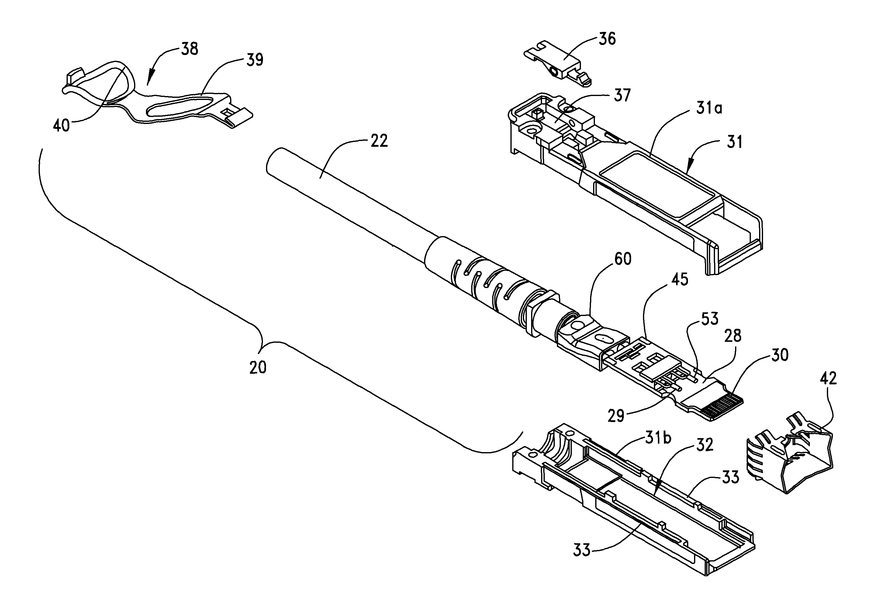
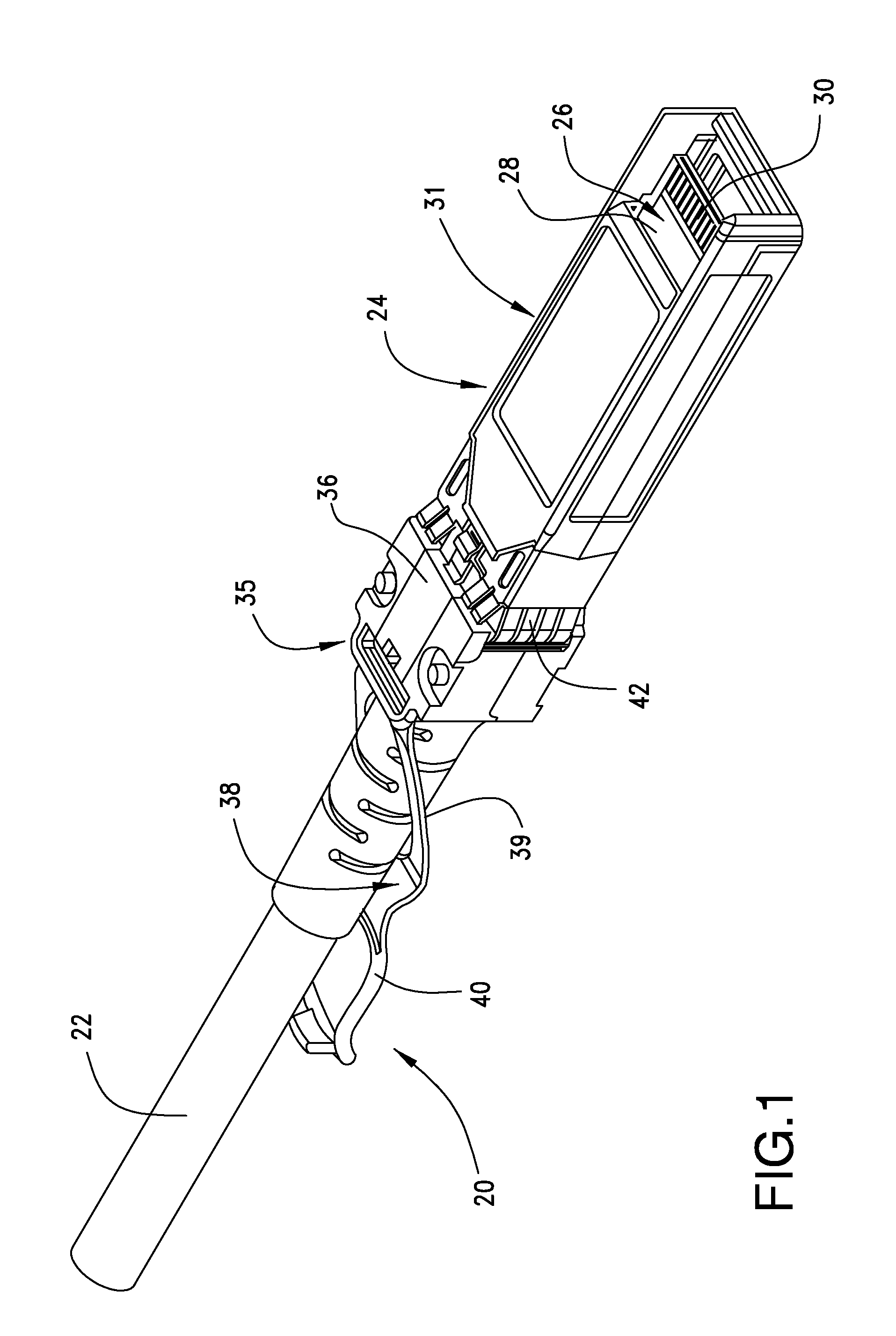
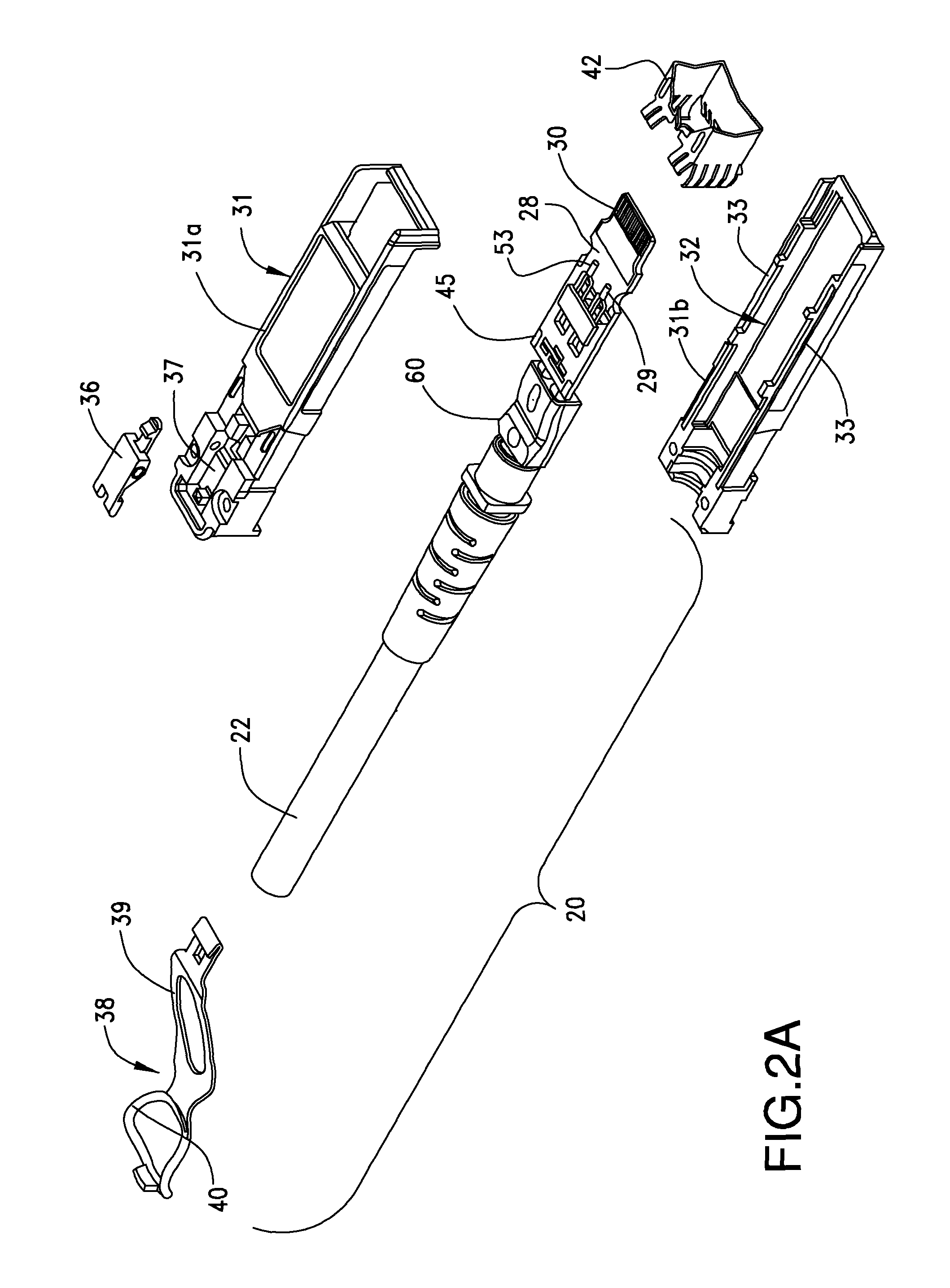
The present patent describes a guide member that helps to transform the orientation of signal wires from vertical to horizontal, and securely holds them in place to reduce strain during termination. The guide member is designed to easily manipulate the wires during attachment to a circuit board, and facilitates handling of the breakout portion of the cable. The guide member has twisting walls to reorient the wire pairs, and is made of a settable material, such as hot melt adhesive, which is injected into the guide member to form a solid structure and support the wires. The guide member is designed to be easily inserted into a connector housing. Overall, the guide member provides stress relief to the wires and makes the termination process easier.

Problems solved by technology

Furthermore, it is common to have the inner wires of the cable extend along a preselected length during termination which is unsupported.
The need for specialized equipment also increases the cost of the connector and even with the jig, the wires are terminated to the edge card in an unsupported state and then a supporting plastic or other moldable material is injected around them and portions of the paddle card, after the termination of the cable wire pairs to the edge card.
Hence, there presently appears not to be any reliable way of orienting and supporting the cable wires in a desirable orientation prior to the termination thereof to the connector edge card.

Method used


Image

  • Connector guide for orienting wires for termination
  • Connector guide for orienting wires for termination
  • Connector guide for orienting wires for termination

Examples


Embodiment Construction

[0027]While the Present Disclosure may be susceptible to embodiment in different forms, there is shown in the Figures, and will be described herein in detail, specific embodiments, with the understanding that the Present Disclosure is to be considered an exemplification of the principles of the Present Disclosure, and is not intended to limit the Present Disclosure to that as illustrated.

[0028]As such, references to a feature or aspect are intended to describe a feature or aspect of an example of the Present Disclosure, not to imply that every embodiment thereof must have the described feature or aspect. Furthermore, it should be noted that the description illustrates a number of features. While certain features have been combined together to illustrate potential system designs, those features may also be used in other combinations not expressly disclosed. Thus, the depicted combinations are not intended to be limiting, unless otherwise noted.

[0029]In the embodiments illustrated in ...


PUM


Abstract

A guide member is provided for use with a multi-wire plug connector. It has an elongated body with multiple wire pathways extending through it in a torturous path so that wires inserted into one end of the guide member in a first orientation are twisted into a second orientation that is different than the first orientation. The guide member body is formed of two parts and one of the parts has ports for the injection of a settable compound, such as a hot melt adhesive to hold the guide member parts together as well as the wires in place within the guide member.

Description

BACKGROUND OF THE PRESENT DISCLOSURE[0001]The Present Disclosure relates generally to plug connectors, and more particularly to plug connectors with an improved wire termination aspect. The technology industry is ever growing and the need for more technology infrastructure, such as more routers and servers, exists in order to utilize internet access to its full capability.[0002]Routers and servers and storage machines are interconnected by high speed connector assemblies in the form of cables having connectors, typically plug connectors, which are terminated to their ends. These connectors are designed for high speed data transmission and typically include a cable that holds a plurality of pairs of twin-axial wires. Twin-axial wires have two signal transmission wires that cooperatively transmit differential signals. A ground or drain wire is associated with each such pair and the twin-axial wires and a drain wire comprise each such signal transmission pair. The twin-axial wires are ...

Claims


Application Information

Patent Timeline
Patent Type & Authority Patents(United States)
IPC IPC(8): H01R12/00H01R12/53H01R13/502H01R13/58H01R13/6463H01R13/66
CPCH01R13/502H01R12/53H01R13/5804H01R13/6658H01R13/6463
Inventor LLOYD, BRIAN KEITHCRANE, JOHN R.
Owner MOLEX INC
Learn More